Lighting apparatus for guiding light onto a light polymerizable piece to effect hardening thereof

a light polymerizable and light-guided technology, which is applied in lighting and heating apparatus, optical radiation measurement, instruments, etc., can solve the problems of not being able to achieve full hardening, not at all hardening of the deeper layer, and at best only incomplete hardening, etc., to achieve a large surface area, improve focusing as a result of the tight arrangement of the chips to one another, and improve the effect of installation density

Inactive Publication Date: 2006-02-21
IVOCLAR VIVADENT AG
View PDF29 Cites 32 Cited by
  • Summary
  • Abstract
  • Description
  • Claims
  • Application Information

AI Technical Summary

Benefits of technology

[0015]In a further modified embodiment of the lighting apparatus of the present invention, it is provided that the metallic reflection region lying between the LED-chips is substantially smaller than the LED-chips themselves. As reflection areas, there can be deployed one of the LED-chips with its metallic over surface or, on the other hand, a plural arrangement of the chips in a surrounding manner around the area, which then exhibits a desirably large surface. This approach offers the advantage that the focusing as a result of the tight arrangement of the chips to one another is better. However, in connection with a configuration of sunken LED-chips having a right-angled configuration of the separation walls, the installation density is particularly favorably high, if right-angled chips are used. The surface portion of the LED-chips on the surface, which is covered by a plural arrangement, can result in, for example, 60% coverage or, even, in connection with a flat reflection layer, reach 90%, whereby the multiple arrangement does not calculate in the surrounding surface.
[0016]It is particularly advantageous if the LED-chips in their plural arrangement are arranged in immediately neighboring contact to the mass which is to be completely hardened. In connection with this approach there arises for the first time the possibility to irradiate a predetermined area of the restoration piece with a selected LED-light source. This approach permits, for example, a more intensive irradiation of the middle and typically deeper lying regions of the restoration piece. The hardening then follows generally so that the central region completely hardens. A shrinking or contraction at this location of the restoration piece is, however, not critical with respect to edge spalling formation, in that, at this point in time, the edge area has not been completely hardened. This represents an especially advantageous progress in the state of the art in contrast to the heretofore known uniform hardening processes, whereby edge spalling formation is drastically reduced or is even completely avoided by use of the lighting apparatus of the present invention.
[0017]In accordance with a further, particularly advantageous embodiment of the lighting apparatus of the present invention, it is provided that a plurality of the LED-chips are provided in such a compact arrangement having a small dimensional area that, at least in connection with larger; and to this extent, especially critical restoration pieces, the light emissions are directed onto the central region. The material to be polymerized has a light distributing partitioning property, so that, in connection with the irradiation of the central area, the edge areas are also irradiated at a reduced intensity. Also, this type of deployment of the lighting apparatus of the present invention makes possible, at the least, an avoidance of the tendency towards edge spalling formation.

Problems solved by technology

However, the operational tension reaches at least 3.5 kV and a corresponding activation device is required so that such lamps are not suitable for deployment in the dental practice, at least insofar as hand operable devices are concerned.
However, deeper lying layers are not at all hardened or, at most, only incompletely hardened.
The known lighting apparatus lead to restoration results that are compromised by, or suffer from, in part, edge spalling problems.

Method used


Image

  • Lighting apparatus for guiding light onto a light polymerizable piece to effect hardening thereof
  • Lighting apparatus for guiding light onto a light polymerizable piece to effect hardening thereof
  • Lighting apparatus for guiding light onto a light polymerizable piece to effect hardening thereof

Examples


Embodiment Construction

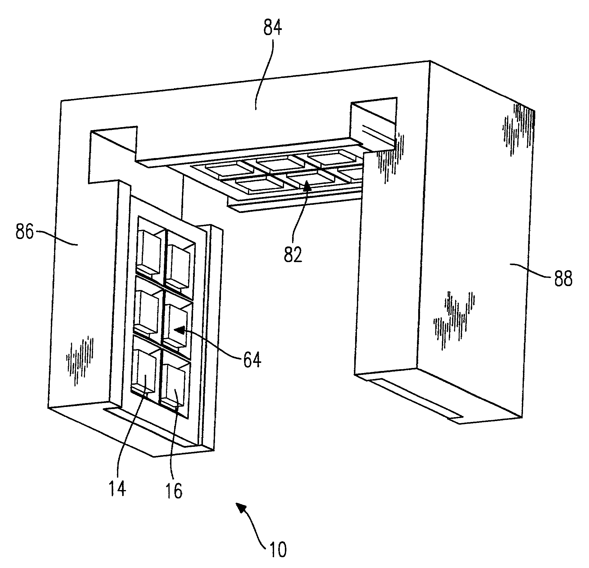
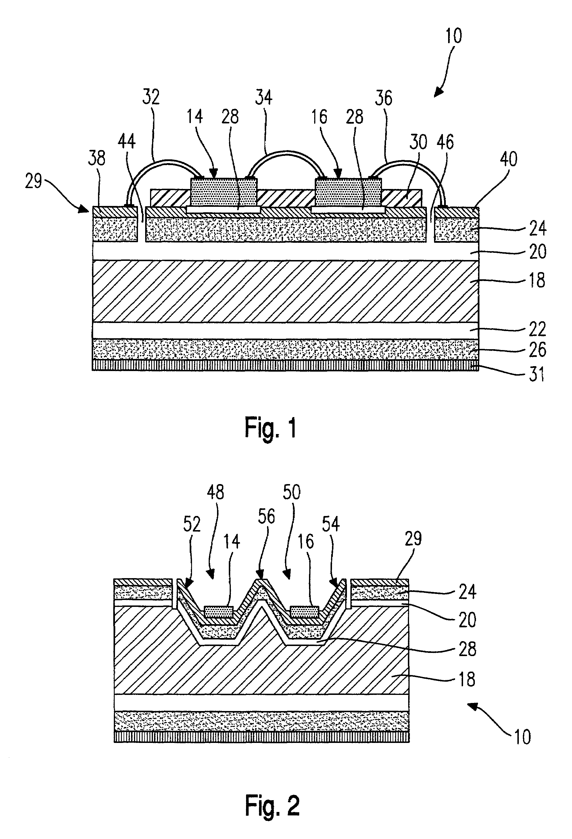
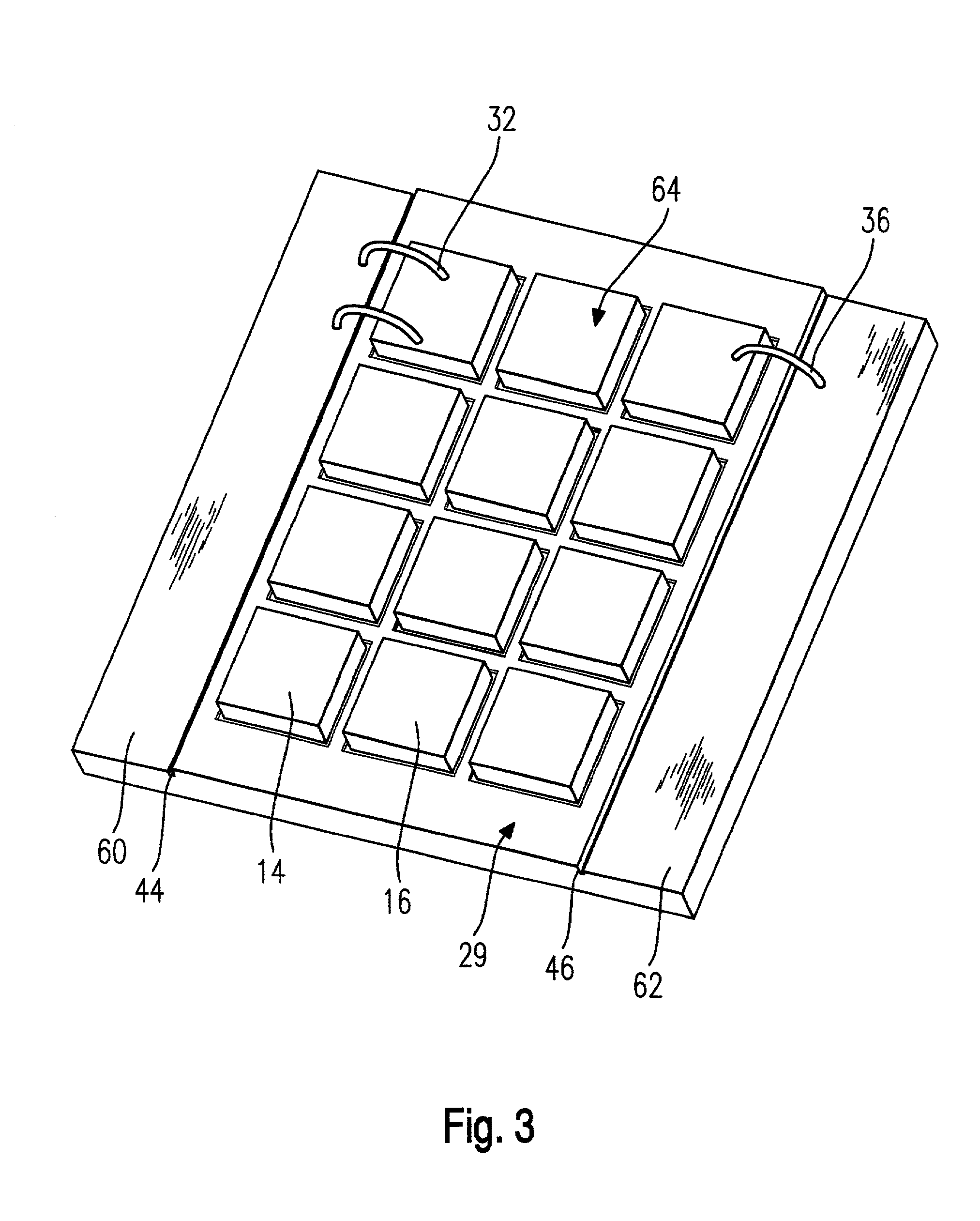
[0029]In FIG. 1, a substantial portion of one embodiment of the lighting apparatus of the present invention, hereinafter designated as the lighting apparatus 10, is shown. The lighting apparatus comprises in this schematically shown representation two light sources 14 and 16. The light sources 14 and 16 are configured as LED-chips and include a surface of 1 mm×1 mm and a thickness of 100 micrometers, which are shown in FIG. 1 in an exaggerated manner in order to promote clarity of the represented lighting apparatus embodiment.

[0030]The light sources 14 and 16 are disposed on a substrate 18 which, in the illustrated embodiment, is a silicon wafer. The layer thickness of the wafer is 500 micrometers so that, to the extent of the representation in FIG. 1, the thickness of the wafer is shown in exaggerated manner. A wafer of this type can be produced in a conventional manner as a disk having a diameter of, for example, 10 centimeters and, in an integrated production process, numerous li...


PUM


Abstract

A lighting apparatus for dental purposes having plurality of light sources supported on semi-conductor bases, which are mounted on a substrate is provided. The lighting apparatus includes a reflective over surface encircling the light sources which reflects visible light. The lighting apparatus may be deployed in a light hardening device as a light source unit with the emitted light beams being conducted, in particular, by a prismatic body, to a light guiding conduit.

Description

CROSS-REFERENCE TO RELATED APPLICATIONS[0001]This application claims foreign priority benefits under 35 U.S.C. §119(a)–(d) from German patent application ser. no. 101 25 341.9 filed May 23, 2001. In addition, this application claims the benefit under 35 U.S.C. §119(e) of U.S. provisional patent application Ser. No. 60 / 305,121 filed Jul. 13, 2001.BACKGROUND OF THE INVENTION[0002]The present invention relates to a lighting apparatus for guiding light onto a light polymerizable piece to effect the hardening thereof.[0003]Light devices have been deployed for, among other applications, dental applications in which a light polymerizable plastic is hardened by irradiation with light. In order to achieve a high light density, energy rich light sources are typically deployed such as halogen glow lamps, xenon photoflash, or even high-tension discharge lamps. The high-tension discharge lamps have, in fact, an especially high light intensity and, thereby, a correspondingly high light density. H...

Claims


Application Information

Patent Timeline
Patent Type & Authority Patents(United States)
IPC IPC(8): A61C3/00A61C13/15A61C19/00H01L25/075H01L33/60
CPCA61C19/003A61C19/004H01L25/0753H01L33/60H01L2224/45147H01L2224/48091H01L2224/73265H01L2924/10253H01L2224/49175H01L2924/01047H01L2224/48137H01L2924/00H01L2924/00014H01L2224/85439H01L2924/00011H01L2924/01033
Inventor PLANK, WOLFGANGROHNER, GOTTFRIED
Owner IVOCLAR VIVADENT AG
Why Eureka
Try Eureka