Supercharge Your Innovation With Domain-Expert AI Agents!

Horizontal engraving and milling machine special for tire mold and using method of horizontal engraving and milling machine

A tire mold, engraving and milling machine technology, applied in the direction of milling machines, milling machine equipment, manufacturing tools, etc., can solve the problems that it is difficult to ensure the overall printing effect, low degree of automation, cumbersome operation, etc., to ensure consistency and aesthetics, The effect of improving the degree of automation and improving the overall efficiency

Inactive Publication Date: 2018-07-24
SHANDONG YUNFENG CNC TECH CO LTD
View PDF0 Cites 10 Cited by
  • Summary
  • Abstract
  • Description
  • Claims
  • Application Information

AI Technical Summary

Problems solved by technology

[0004] 1. The font processing process is all manual, cumbersome operation, low degree of automation, long processing time and low efficiency
[0005] 2. The position reference of the font should be consistent with the processing reference of the upper and lower surfaces, and it is difficult to ensure that it is consistent with the machining reference by manual operation
[0006] 3. The arrangement of the fonts relies on manual operation of the font samples to be printed in sequence, the bit error rate is high, and it is difficult to ensure the overall printing effect, which affects the appearance

Method used


Image

  • Horizontal engraving and milling machine special for tire mold and using method of horizontal engraving and milling machine
  • Horizontal engraving and milling machine special for tire mold and using method of horizontal engraving and milling machine
  • Horizontal engraving and milling machine special for tire mold and using method of horizontal engraving and milling machine

Examples


Embodiment Construction

[0035] The following will clearly and completely describe the technical solutions in the embodiments of the present invention with reference to the accompanying drawings in the embodiments of the present invention. Obviously, the described embodiments are only some, not all, embodiments of the present invention. Based on the embodiments of the present invention, all other embodiments obtained by persons of ordinary skill in the art without making creative efforts belong to the protection scope of the present invention.

[0036] The object of the present invention is to provide a special horizontal engraving and milling machine for tire molds and its use method, so as to solve the technical problems in the above-mentioned prior art.

[0037] In order to make the above objects, features and advantages of the present invention more comprehensible, the present invention will be further described in detail below in conjunction with the accompanying drawings and specific embodiments....


PUM


Abstract

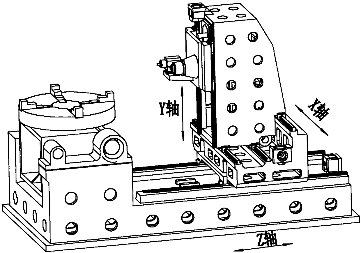
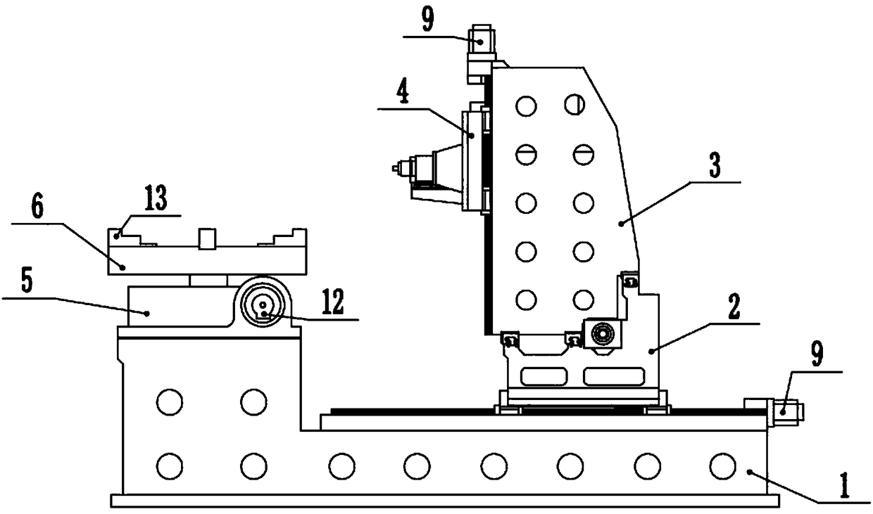
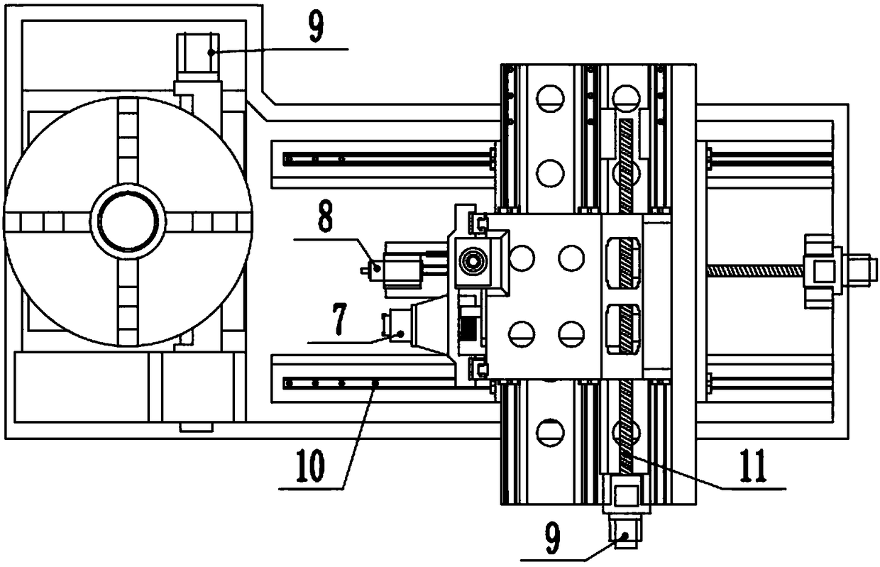
The invention discloses a horizontal engraving and milling machine special for a tire mold and a using method of the horizontal engraving and milling machine. A first linear driving mechanism drives aZ-axis sliding piece to slide on a base along a left-right direction; a second linear driving mechanism drives a X-axis sliding piece to slide on the Z-axis sliding piece along a front-back direction; a third linear driving mechanism drives a Y-axis sliding piece to slide on the X-axis siding piece along an up-down direction; a first rotating mechanism drives a rotary working table to rotate on the base; a second rotating mechanism drives the first rotating mechanism and the rotary working table to axially rotate on the base along the front-back direction; a controller respectively controls the movement of the first linear driving mechanism, the second linear driving mechanism, the third linear driving mechanism, the first rotating mechanism and the second rotating mechanism; the Y-axis sliding piece is provided with an engraving and milling machining head; the engraving and milling machining head comprises a mechanical main shaft and a frequency-variable electric main shaft. Comparedwith the prior art, the horizontal engraving and milling machine disclosed by the invention has the advantages that the machining efficiency and the machining accuracy are increased, the labor intensity of workers is reduced, and consistency and attractiveness of a whole machining effect are ensured.

Description

technical field [0001] The invention relates to the technical field of tire mold processing devices, in particular to a tire mold-specific horizontal engraving and milling machine and a method for using the same. Background technique [0002] The tire mold is an important tool in the tire manufacturing process. Various mechanisms are usually arranged on the outer shell of the tire mold to facilitate classification and identification or to facilitate the processing and manufacturing of tires. The upper and lower surfaces of the tire mold shell are usually provided with processing positions marked on drawings such as exhaust grooves, positioning block grooves, and positioning holes. The outer surface of the tire mold shell is usually provided with descriptive texts about specifications, models and other information. These texts are small and large in number, and it is difficult to process them by ordinary methods. [0003] In the prior art, for the above-mentioned structure o...

Claims


Application Information

Patent Timeline
IPC IPC(8): B23C1/04B23C3/00B23Q1/25B23Q5/34B23Q5/40
CPCB23C1/04B23C3/00B23Q1/25B23Q5/34B23Q5/40
Inventor 刘浩涛徐永强
Owner SHANDONG YUNFENG CNC TECH CO LTD
Features
  • R&D
  • Intellectual Property
  • Life Sciences
  • Materials
  • Tech Scout
  • Unparalleled Data Quality
  • Higher Quality Content
  • 60% Fewer Hallucinations
Learn More