Solar heat collection and ventilation system for passive house

A solar heat collection and ventilation system technology, applied in the field of solar heat collection and ventilation systems, can solve problems such as poor heating stability, overheating, and insufficient natural ventilation power, and achieve strong heat collection and ventilation capabilities, alleviate indoor overheating, and improve indoor heat. environmental effects

Pending Publication Date: 2018-07-24
NANJING UNIV OF TECH
View PDF8 Cites 15 Cited by
  • Summary
  • Abstract
  • Description
  • Claims
  • Application Information

AI Technical Summary

Problems solved by technology

[0006] The purpose of the present invention is to provide a passive house-oriented solar heat collection and ventilation system to solve the problems of indoor overheating in summer, insufficient natural ventilation power, and poor heating stability in conventional passive houses

Method used


Image

  • Solar heat collection and ventilation system for passive house
  • Solar heat collection and ventilation system for passive house
  • Solar heat collection and ventilation system for passive house

Examples


specific Embodiment approach 1

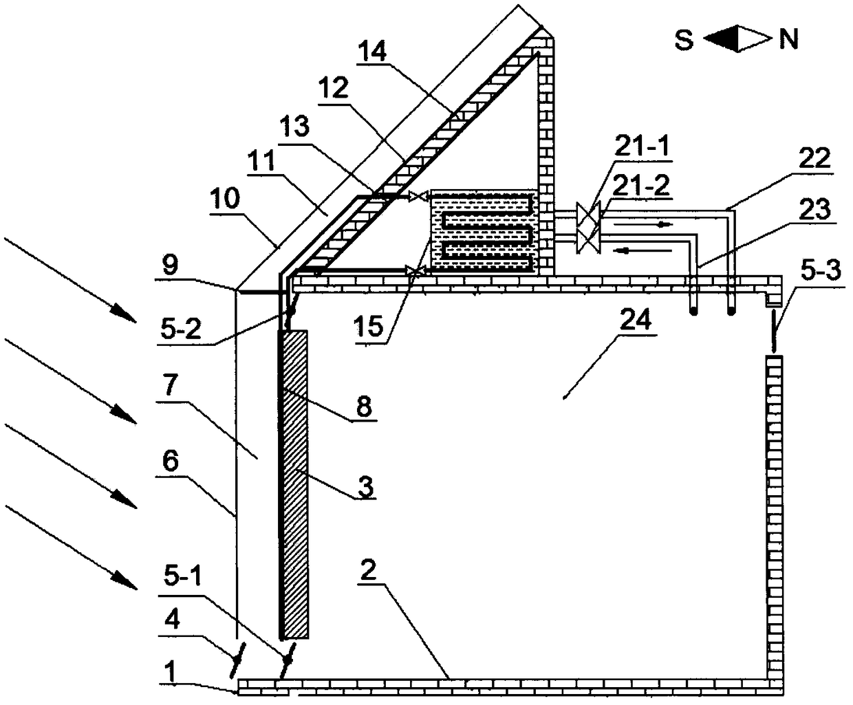
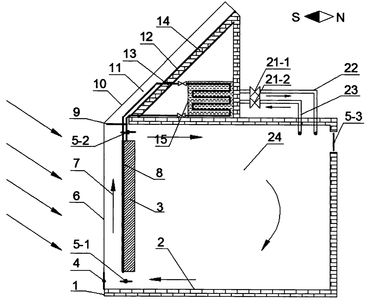
[0028] Specific implementation mode one: combine figure 1 Explanation, the passive house-oriented solar heat collection and ventilation system of this embodiment includes a passive solar house 1, a TROMBE wall transparent cover 6, an air baffle 9, a solar chimney transparent cover 10, a two-phase closed thermosiphon 8, and a TROMBE wall Air interlayer 7, solar chimney heat channel 11, water tank 15; described passive solar house 1 includes heavy wall body 3, enclosure structure 2, passive house interior 24, inclined roof 14; inclined roof 14 is adjacent to solar chimney heat channel 11 side A heat absorbing plate 12 is arranged, and a heat insulating plate 13 is provided on the opposite side.

[0029] In this embodiment, the bottom of the transparent cover plate 6 of the TROMBE wall is provided with a damper 4, and the upper and lower sides of the heavy wall 3 are respectively provided with an indoor air inlet 5-2 and an indoor air outlet 5-1. Tuyere 5-3.

specific Embodiment approach 2

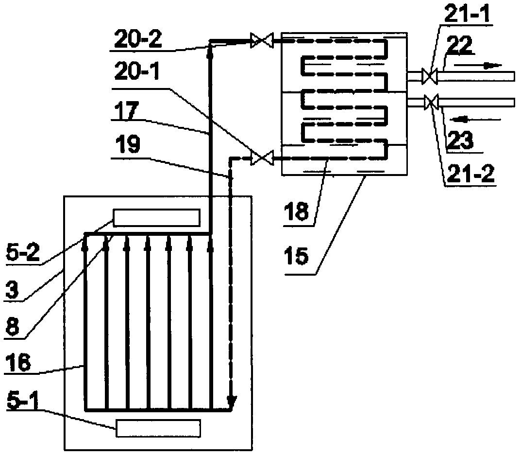
[0030] Specific implementation mode two: combination Figure 1-Figure 2 Explain that the two-phase closed thermosiphon 8 in this embodiment is composed of an evaporator 16, a condenser 18, an ascending gas pipe 17, a descending liquid pipe 19, and a valve 20-1 and a valve 20-2. The evaporator 16 is located in the heavy On the outer surface of the body of wall 15, the condenser is placed in the water tank 15. The water tank 15 is connected to the indoor 24 through the water inlet pipe 23, the water outlet pipe 22, the water outlet pipe valve 21-1, and the water inlet pipe valve 21-2.

specific Embodiment approach 3

[0031] Specific implementation mode three: combination Figure 1-Figure 2 Note that the two-phase closed thermosiphon 8 in this embodiment is a copper tube. With such setting, it is easy to install and use, strong, strong in corrosion resistance, and good in heat transfer effect. Others are the same as in the second embodiment.


PUM


Abstract

The invention discloses a solar heat collection and ventilation system for a passive house. The solar heat collection and ventilation system is composed of a TROMBE wall, a slanting roof solar chimneyand a two-phase closed type thermosiphon, wherein the TROMBE wall comprises a transparent glass cover plate, an air interlayer, a heavy wall, an air valve, a heavy wall upper indoor air inlet and a heavy wall lower indoor air outlet; the slanting roof solar chimney is composed of a transparent cover plate, an air interlayer, a slanting roof, a heat absorption plate and a heat insulation plate. Anair baffle is arranged at the junction between the slanting roof solar chimney and the TROMBE wall; the two-phase closed type thermosiphon is composed of an evaporator, a condenser, a rising air pipe, a downflow liquid pipe and control valves. Through the solar heat collection and ventilation system, the defects that a traditional heat collection and ventilation system is single in function and poor in effect are overcome. The solar heat collection and ventilation system has the advantages of being high in heat collection and ventilation ability, diversified in function and easy to operate and not consuming energy. The solar heat collection and ventilation system is used for conducting natural ventilation and preventing indoor overheat in summer and making domestic hot water and can achieve solar hot air heating and fresh air preheating in winter.

Description

Technical field [0001] The invention relates to a solar energy utilization technology, which belongs to the field of energy utilization technology, in particular to a solar heat collection and ventilation system for passive houses. Background technique [0002] With the continuous development of urbanization in my country, the demand for energy has increased sharply, and the environmental problems caused by energy consumption have become increasingly serious. Energy conservation and emission reduction have become an inevitable requirement to ensure the healthy and stable development of my country's economy and society. Making full use of renewable energy to create a comfortable and healthy building thermal environment and reducing energy consumption has become one of the main directions for the development of the HVAC industry. [0003] In 2017, the National Development and Reform Commission, the National Energy Administration and other departments jointly issued the "Winter...

Claims


Application Information

Patent Timeline
Patent Type & Authority Applications(China)
IPC IPC(8): F24F5/00F24F7/00F24F13/26F24F13/30F24S20/66F24S10/30F24S10/95F24S60/10E04B7/02
CPCF24F5/0046F24F7/00F24F13/26F24F13/30E04B7/02F24F2005/0064F24F2007/004F24F2007/0025Y02B10/20Y02A30/272
Inventor 刘慧芳袁晓航刘金祥周斌袁晓磊
Owner NANJING UNIV OF TECH
Why Eureka
Try Eureka