

Roller type low friction vertical loading system with tracking function
A technology with vertical loading and tracking functions, applied in the testing of mechanical components, testing of machine/structural components, measuring devices, etc., it can solve the problems of displacement difference, lack of function, and the inability of the roller table to fully buffer. , to ensure a stable effect
- Summary
- Abstract
- Description
- Claims
- Application Information
AI Technical Summary
Problems solved by technology
Method used
Image

Examples
Embodiment Construction
[0019] In order to further understand the invention content, characteristics and effects of the present invention, the following examples are given, and detailed descriptions are as follows in conjunction with the accompanying drawings:
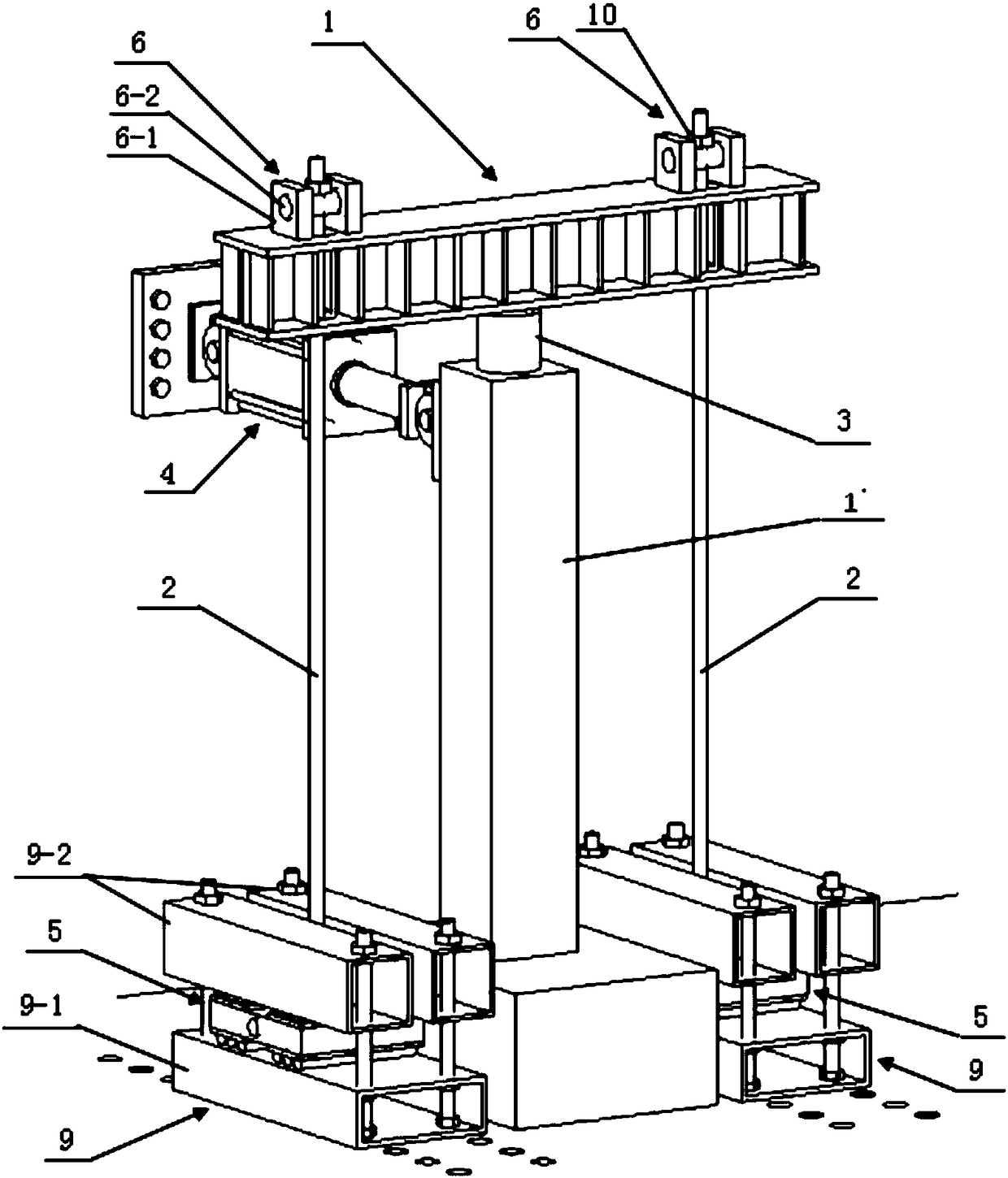
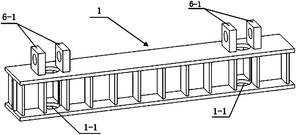
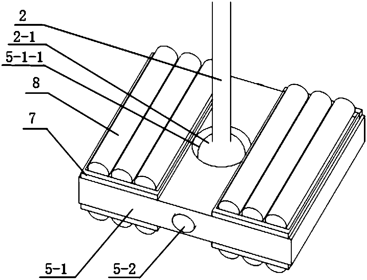
[0020] See Figure 1-3 , a roller-type low-friction vertical loading system with tracking function, including a beam 1, two tie rods 2, a hydraulic jack 3 for applying a vertical load, an actuator 4 for applying a horizontal load, and two sets of lower hinged seats 5 . The upper ends of the two tie rods pass through the parts close to both ends of the beam respectively, and the lower ends of the two tie rods are respectively connected with two sets of lower hinge seats. The place between the two tie rods is where the test member is placed, and the hydraulic jack is placed at 1' of the test member. Above, and in contact with the lower end of the beam, the actuator is fixedly installed on the vertical wall of the laboratory, and connected to t...
PUM
 Abstract
Description
Claims
Application Information