
RF attenuation patch equivalent attenuation control circuit

A technology of equivalent attenuation and control circuit, which is applied in the field of radio frequency transmission, can solve problems such as gain flatness and return loss deterioration, return loss, insertion loss deviation, and increase the difficulty of designing radio frequency transmission products, so as to avoid design redundancy In addition, to avoid the effect of attenuation deviation

Pending Publication Date: 2018-07-24
成都芯通软件有限公司
View PDF0 Cites 1 Cited by
  • Summary
  • Abstract
  • Description
  • Claims
  • Application Information

AI Technical Summary

Problems solved by technology

[0002] In the radio frequency transmission system, it is usually necessary to use attenuation inserts or EQ slope inserts to adjust the radio frequency signal, but due to the discrete factors of attenuation devices, even if the attenuation inserts or EQ slope inserts of the same manufacturer have different specifications, the return loss There is also a big difference between the error and the standard attenuation, especially in the field construction application, the attenuation insert or the EQ slope insert used may be provided by many different manufacturers, because the processing technology and design scheme of different manufacturers are different, It will lead to uncertain deviations in the return loss and insertion loss of the attenuation insert or the EQ slope insert itself, and when these deviation factors are cascaded with the radio frequency transmission system, the attenuation accuracy or attenuation slope, Indicators such as gain flatness and return loss will deteriorate or fail to meet the requirements. Therefore, in order to reduce the impact on the radio frequency transmission system, in actual use, there are often constraints on the manufacturer and model used, and it is also necessary to control the radio frequency transmission system. Compatible design of the system increases the difficulty of designing RF transmission products

Method used


Image

  • RF attenuation patch equivalent attenuation control circuit
  • RF attenuation patch equivalent attenuation control circuit
  • RF attenuation patch equivalent attenuation control circuit

Examples


Embodiment 1

[0027] Such as figure 2 The present invention shown uses the schematic diagram of the circuit structure of voltage sampling; In the radio frequency attenuation plug equivalent attenuation control circuit of the present invention, the reference signal source is a voltage source, the voltage source is connected with the input terminal of the plug socket, and the output of the plug socket The terminal is connected with the analog-to-digital conversion module of the microcontroller processing unit. figure 2 The ADC (Analog-to-Digital Converter) in is an analog-to-digital conversion module.

[0028] Specifically, the radio frequency attenuation insert equivalent attenuation control circuit of the present invention further includes a first resistor, a first capacitor and a second resistor. Wherein, the voltage source is connected to the input end of the blade socket through the first resistor, and one end of the first capacitor and the second resistor is connected to the output e...

Embodiment 2

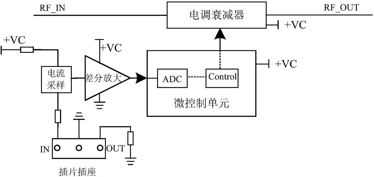
[0031] Such as image 3 The schematic diagram of the circuit structure using current sampling in the present invention is shown; in this embodiment, the radio frequency attenuation insert equivalent attenuation control circuit of the present invention also includes the current sampling module and the differential amplification module, and the reference signal source is a voltage source .

[0032] Wherein, the input end of the blade socket is connected to the voltage source, and its output end is grounded; the current sampling module collects the current flowing through the blade socket, and outputs a corresponding voltage to the differential amplifier module, The differential amplification module amplifies the voltage and transmits it to the analog-to-digital conversion module of the micro control unit.

[0033] Specifically, the radio frequency attenuation insert equivalent attenuation control circuit of the present invention also includes a third resistor and a fourth resis...

Embodiment 3

[0035] Such as Figure 4 Four structural types schematic diagrams of the shown attenuation inserts of the present invention; wherein, Figure 4 a is the equivalent internal circuit of the π-type attenuation insert, Figure 4 b is the equivalent internal circuit of the T-type attenuation insert, Figure 4 c is the equivalent internal circuit of the bridge T-type attenuation insert, Figure 4 d is the equivalent internal circuit with its own slope attenuation insert.

[0036]In actual application, the electronically adjustable attenuator in the equivalent attenuation control circuit of the radio frequency attenuation insert of the present invention has an EQ slope attenuation adjustment function. The present invention has three working modes: first, any one of π-type attenuation inserts, T-type attenuation inserts and bridge T-type attenuation inserts is used, and the micro-control unit controls the ESC attenuation to generate corresponding attenuation. Second, using any one...


PUM


Abstract

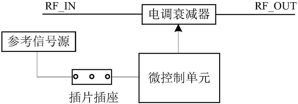
The invention discloses an RF attenuation patch equivalent attenuation control circuit, which comprises a reference signal source, a patch socket, an electrically adjustable attenuator and a micro control unit. The electrically adjustable attenuator is arranged on an RF signal transmission line requiring certain attenuation. The reference signal source is connected to the patch socket, and the attenuation patch inserted into the patch socket is used for attenuating a reference signal outputted by the reference signal source. An analog-to-digital conversion module in the micro control unit is configured to convert the attenuated reference signal into corresponding data. The micro control unit controls the electrically adjustable attenuator to generate an attenuation value equivalent to theattenuation patch according to the converted data. Therefore, the RF attenuation patch equivalent attenuation control circuit can avoid the attenuation deviation between different attenuation patches,and stably generate equivalent attenuation, thereby solving the limitation of applying the attenuation patch to the RF transmission system, and avoiding design redundancy of the RF transmission system. .

Description

technical field [0001] The invention relates to the technical field of radio frequency transmission, in particular to an equivalent attenuation control circuit of a radio frequency attenuation insert. Background technique [0002] In the radio frequency transmission system, it is usually necessary to use attenuation inserts or EQ slope inserts to adjust the radio frequency signal, but due to the discrete factors of attenuation devices, even if the attenuation inserts or EQ slope inserts of the same manufacturer have different specifications, the return loss There is also a big difference between the error and the standard attenuation, especially in the field construction application, the attenuation insert or the EQ slope insert used may be provided by many different manufacturers, because the processing technology and design scheme of different manufacturers are different, It will lead to uncertain deviations in the return loss and insertion loss of the attenuation insert o...

Claims


Application Information

Patent Timeline
IPC IPC(8): G05B19/042
CPCG05B19/0423G05B2219/25257
Inventor 杜椿罗俊
Owner 成都芯通软件有限公司
Learn More