
Fault diagnosis method and apparatus

A fault diagnosis and fault technology, applied to the generation of response errors, instruments, electrical digital data processing, etc., can solve the problems of different availability, inability to effectively eliminate fault causes, long reasoning time, etc.

Active Publication Date: 2018-07-24
BEIJING WATERTEK INFORMATION TECH
View PDF10 Cites 1 Cited by
  • Summary
  • Abstract
  • Description
  • Claims
  • Application Information

AI Technical Summary

Problems solved by technology

Some of the reasons for not providing test passing information are due to the simplification and optimization of inter-system data interfaces and the amount of bus transmission data, and some are due to the different availability of each test passing information under different working modes, and it may also cause some failures in certain system failure states. Unavailability or inaccessibility of BIT pass information for some tests
[0005] Because the real-time fault reports of these systems cannot provide the passing information of the corresponding tests, the methods based on the diagnostic tree or correlation matrix fail, and the information passed by the test cannot be used to effectively troubleshoot the cause of the fault, resulting in a large number of non-faults included in the actual diagnosis results. equipment or device
[0006] In addition, the direct use of correlation matrix in real-time fault diagnosis still has long reasoning time and many temporary resources.

Method used


Image

  • Fault diagnosis method and apparatus
  • Fault diagnosis method and apparatus

Examples


Embodiment Construction

[0039] In order to make the purpose, technical solution and advantages of the present invention more clear, the embodiments of the present invention will be described in detail below in conjunction with the accompanying drawings. It should be noted that, in the case of no conflict, the embodiments in the present application and the features in the embodiments can be combined arbitrarily with each other.

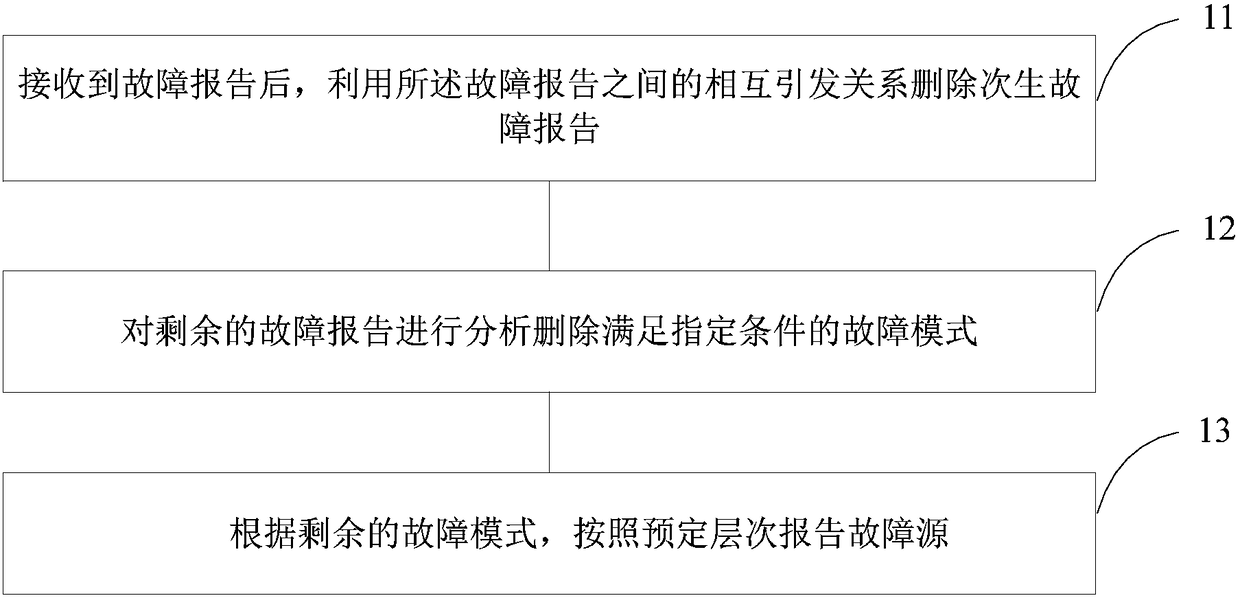
[0040] In order to solve the above problems, the embodiment of the present disclosure proposes a fault diagnosis method, such as figure 1 As shown, the method of the present embodiment includes the following steps:

[0041]Step 11. After receiving the fault report, delete the secondary fault report by using the mutual trigger relationship between the fault reports;

[0042] Step 12, analyzing the remaining fault reports and deleting the fault modes satisfying the specified conditions;

[0043] Step 13. According to the remaining fault modes, report fault sources according t...


PUM


Abstract

The invention discloses a fault diagnosis method and apparatus. The method comprises the steps of receiving fault reports, and deleting secondary fault reports by utilizing a mutual triggering relationship among the fault reports; analyzing the rest of fault reports to delete fault modes meeting a specified condition; and according to the rest of fault modes, reporting fault sources based on predetermined levels. According to the scheme, for a characteristic that test passing information is unavailable due to a reason of system design, working modes, fault blockage or the like in a specific function system, a conventional fault diagnosis method is improved, so that quick and efficient requirements of an actual diagnosis system design process are met.

Description

technical field [0001] Embodiments of the present disclosure relate to but are not limited to the technical field of fault diagnosis, especially a method and device for fault diagnosis. Background technique [0002] Using a diagnosis tree or a correlation matrix to diagnose system faults is a method commonly used in engineering at present. This method uses the test passing branches or test failure branches corresponding to the diagnosis tree nodes to gradually divide the system state set space until When the terminal node of the diagnostic tree is reached, there is no available test to further divide the system state. At this time, the corresponding terminal node of the diagnostic tree is the current state of the system, that is, the diagnosis result or the cause of the failure. [0003] The fault diagnosis method using the correlation matrix is ​​also based on the same principle, the difference is that the correlation matrix can divide the system state collection space from...

Claims


Application Information

Patent Timeline
IPC IPC(8): G06F11/07
CPCG06F11/079
Inventor 陈宁霍鸿文陈静
Owner BEIJING WATERTEK INFORMATION TECH
Learn More