
Outdoor power supply power distribution box

A power distribution, outdoor technology, applied in electrical components, substation/switch layout details, substation/switchgear cooling/ventilation, etc. safety effect

Active Publication Date: 2018-07-24
GUANGDONG DEHUANG ELECTRIC POWER EQUIP
View PDF4 Cites 2 Cited by
  • Summary
  • Abstract
  • Description
  • Claims
  • Application Information

AI Technical Summary

Problems solved by technology

[0002] The distribution box of the distribution transformer is generally set adjacent to the transformer. It is a very important power transmission and distribution equipment for enterprises or power supply users. The existing outdoor power distribution box has a complex structure , the maintenance is very inconvenient, and the overall security is low, which cannot meet the needs of enterprises

Method used


Image

  • Outdoor power supply power distribution box
  • Outdoor power supply power distribution box
  • Outdoor power supply power distribution box

Examples


Embodiment 1

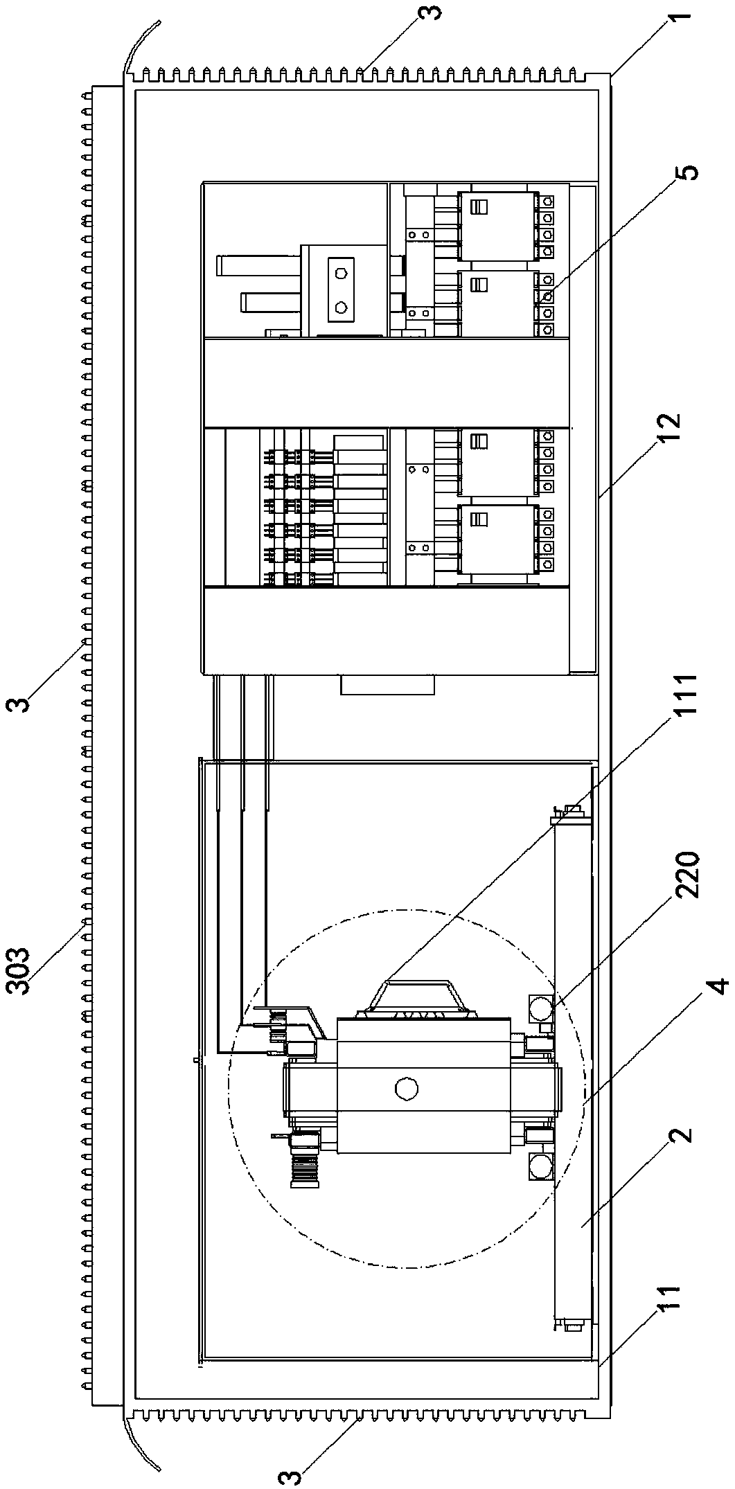
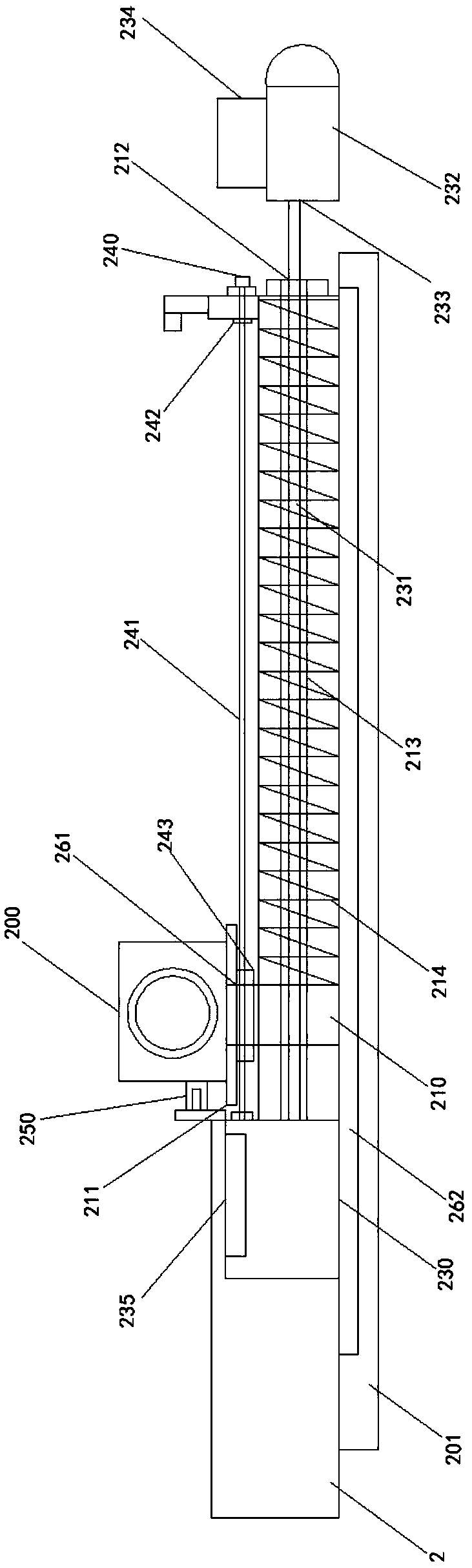
[0023] Embodiment 1: refer to Figure 1-7 , an outdoor power distribution box, comprising an outer box 1, a transformer cabinet 11 adjacently arranged, and a power distribution cabinet 12, a transformer main body 111 is arranged in the transformer cabinet 11, and the transformer main body 111 includes a low-voltage winding and a high-voltage winding And set the cross-flow cooling fan 200 at the bottom of the low-voltage winding, and set supporting brackets 2 corresponding to each group of high-voltage windings or low-voltage windings at the bottom of the low-voltage winding and high-voltage winding, and the supporting brackets 2 are arranged at equal intervals, and the cross-flow cooling fan 200 is placed on the side of the support bracket 2 close to the corresponding high-voltage winding or low-voltage winding.

[0024] The cross-flow cooling fan 200 is slidably installed on the chute of the support bracket 2 through the bracket slider 210, and the cross-flow cooling fan 200 ...

Embodiment 2

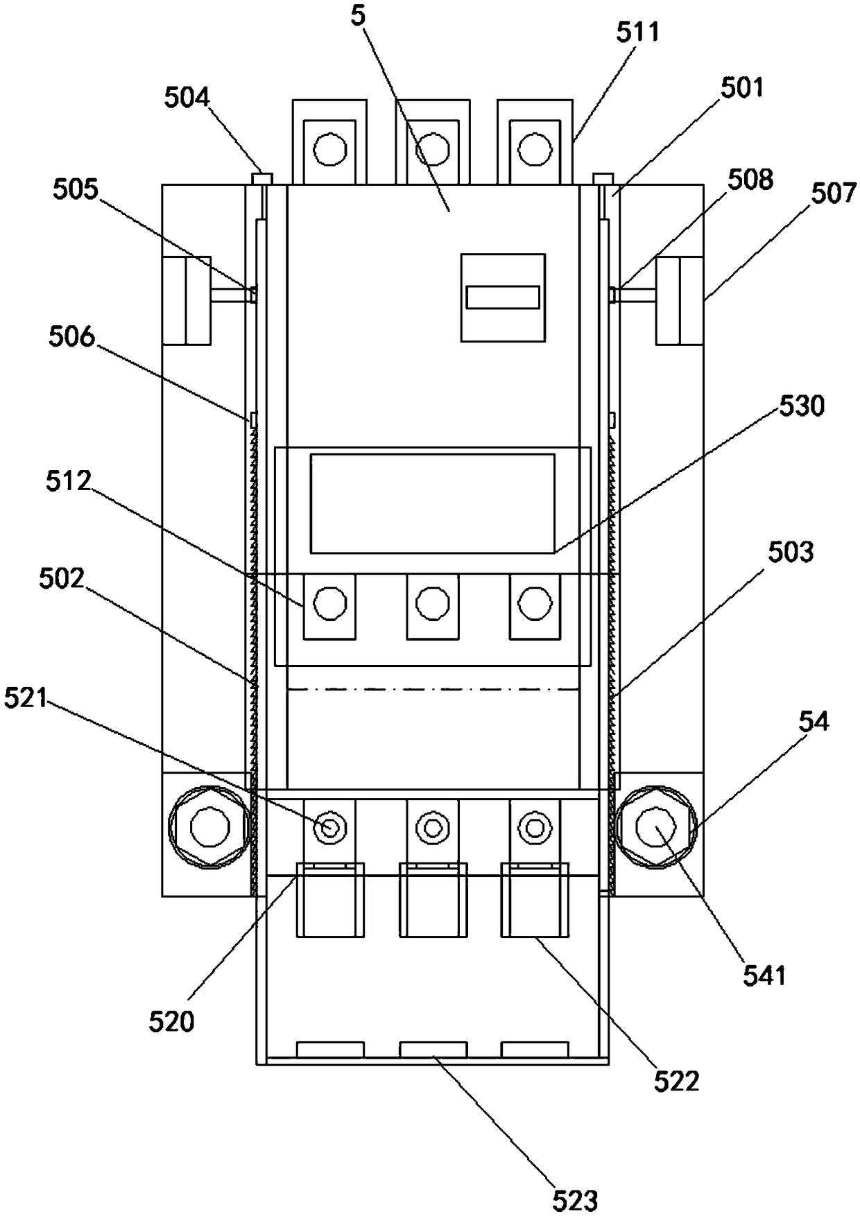
[0033] Embodiment 2: refer to Figure 1-7 , including a transformer cabinet 11 and a power distribution cabinet 12 placed adjacently in the outer box 1. The power distribution cabinet 12 consists of a reactive power compensation room, a main switch room, and an outgoing line control switch room. After the main switch room A busbar room is set at the bottom, the incoming busbar is connected to the incoming line side of the main switch through the first incoming line connection copper plate, the outgoing line side of the main switch is connected to the outgoing line busbar at the bottom of the main switch room, and several groups are set at the bottom of the outgoing line busbar Several groups of outgoing line control switches 5 on the switch bracket.

[0034]The outgoing line busbar is connected to the incoming line connector 511 on the incoming line side of the outgoing line control switch 5, at least one side of one outgoing line control switch 5 is provided with a guide notc...

Embodiment 3

[0042] Embodiment 3: refer to Figure 1-7 , an outdoor power distribution box, including a transformer cabinet 11 and a power distribution cabinet 12 placed adjacently in an outer box 1, the side plate 2 of the outer box 1 is provided with a light pollution barrier layer 3, and the light pollution barrier The barrier layer 3 consists of several groups of transverse grooves 302 arranged at equal intervals in the first square frame 301, and is provided with transverse struts 303 slightly smaller than the diameter of the transverse grooves 302, and the transverse struts 312 correspond to the arrangement of the transverse grooves In the square second frame 311, the diameter of the second frame 311 is larger than the diameter of the first frame 301 and surrounds the above-mentioned first frame 301, and the transverse struts 312 of the second frame 311 can be fitted and installed on the corresponding first frame 301 In the transverse groove 302.

[0043] Corresponding to the four e...


PUM


Abstract

The invention relates to the field of low-voltage power distribution research and development design, particularly an outdoor power supply power distribution box. A technical scheme is adopted as follows: a plurality groups of transverse grooves, which are distributed in a square first framework at equal distances, are formed in a side plate of an outer box body; transverse supporting rods which are slightly smaller than the transverse groove diameters are provided; the transverse supporting rods are arranged in a square second formwork corresponding to the transverse grooves; the diameter ofthe second framework is greater than that of the first framework, and the second framework surrounds the first framework; top rods and guiding axial holes matched with the top rods are arranged on theinner side, corresponding to four end parts of the second framework, of the outer box body; a top rod shaft sleeve with an opening in one end and a bottom at the other end is arranged in each of thefour end parts of the second framework separately; sealing rubber sleeves or spiral compression sleeves are arranged between the guiding axial holes and the corresponding top rod shaft sleeves; and convex cutting parts are arranged on the other sides, opposite to the outer box body, of the transverse supporting rods or between the adjacent transverse grooves. The outdoor power supply power distribution box has the advantages of preventing light pollution and further preventing pasting of adlet, and removing big adlet automatically.

Description

technical field [0001] The invention relates to the field of research and development and design of low-voltage power distribution, in particular to an outdoor power distribution box. Background technique [0002] The distribution box of the distribution transformer is generally set adjacent to the transformer. It is a very important power transmission and distribution equipment for enterprises or power supply users. The existing outdoor power distribution box has a complex structure , maintenance is very inconvenient, and the overall security is low, which cannot meet the needs of enterprises. SUMMARY OF THE INVENTION [0003] The purpose of the present invention is to provide an outdoor power distribution box, specifically to provide an outdoor power distribution box with high intrinsic safety. [0004] To achieve the above object, the present invention adopts the following technical solutions: [0005] An outdoor power distribution box, including a transformer cabinet...

Claims


Application Information

Patent Timeline
IPC IPC(8): H02B1/46H02B1/48H02B1/56H02B1/54
CPCH02B1/46H02B1/48H02B1/54H02B1/565
Inventor 黄思玉
Owner GUANGDONG DEHUANG ELECTRIC POWER EQUIP
Features
  • Generate Ideas
  • Intellectual Property
  • Life Sciences
  • Materials
  • Tech Scout
  • Unparalleled Data Quality
  • Higher Quality Content
  • 60% Fewer Hallucinations
Learn More