A drum sealing device of a drum type chip removal machine, a drum, and a drum chip removal machine

A technology of sealing device and chip removal machine, which is applied in the direction of engine sealing, mechanical equipment, engine components, etc., can solve problems such as sealing failure, achieve reliable sealing device, avoid frequent replacement of sealing parts, and solve the effect of sealing failure

Active Publication Date: 2020-08-21
NINGXIA KOCEL MACHINE TOOL ACCESSORIES
View PDF11 Cites 0 Cited by
  • Summary
  • Abstract
  • Description
  • Claims
  • Application Information

AI Technical Summary

Problems solved by technology

The sealing device solves the problem of seal failure, uses high-pressure cutting fluid as the sealing element, and avoids the use of vulnerable parts such as end face water seals and packings, and the sealing method is very reliable

Method used


Image

  • A drum sealing device of a drum type chip removal machine, a drum, and a drum chip removal machine
  • A drum sealing device of a drum type chip removal machine, a drum, and a drum chip removal machine
  • A drum sealing device of a drum type chip removal machine, a drum, and a drum chip removal machine

Examples


Embodiment 1

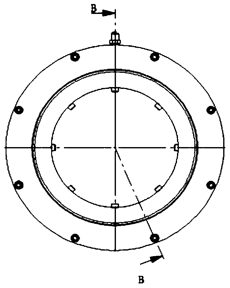
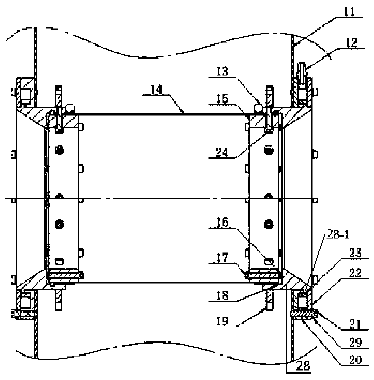
[0025] Such as figure 1 with figure 2 As shown, a drum sealing device of a drum type chip removal machine, the drum sealing device is symmetrically installed on the two outer sides of the drum, and the structure includes: an inner ring 15 located on the outer side of the drum, and a filter fixed on the outer wall of the inner ring through a throat hoop 13 The net 14, which constitutes the main structure of the drum, is used to filter the cutting fluid. The moving ring 28 fixedly connected to the inner ring through the second bolt 24 is assembled with the main side wall 11 of the chip removal machine. The outer wall of the moving ring is located at the chip removal A convex ring 28-1 is provided between the side wall of the main body and the front end of the moving ring, and the inner wall is composed of a cylindrical hole and a conical hole, wherein the inner wall of the cylindrical hole is in contact with the outer wall of the inner ring, and the inner diameter of the conica...

Embodiment 2

[0028] Such as figure 1 with figure 2 As shown, the drum of a drum chip removal machine is composed of the drum sealing device in Embodiment 1. The outer wall of the moving ring 28 of the drum sealing device is provided with a sprocket 19, and the sprocket 19 is located on the side wall of the main body of the chip removal machine. The inner side, close to the end of the moving ring, is fixed to the filter screen 14 on the outer wall of the inner ring through the throat hoop 13, which constitutes the main structure of the drum and is used to filter the cutting fluid.

Embodiment 3

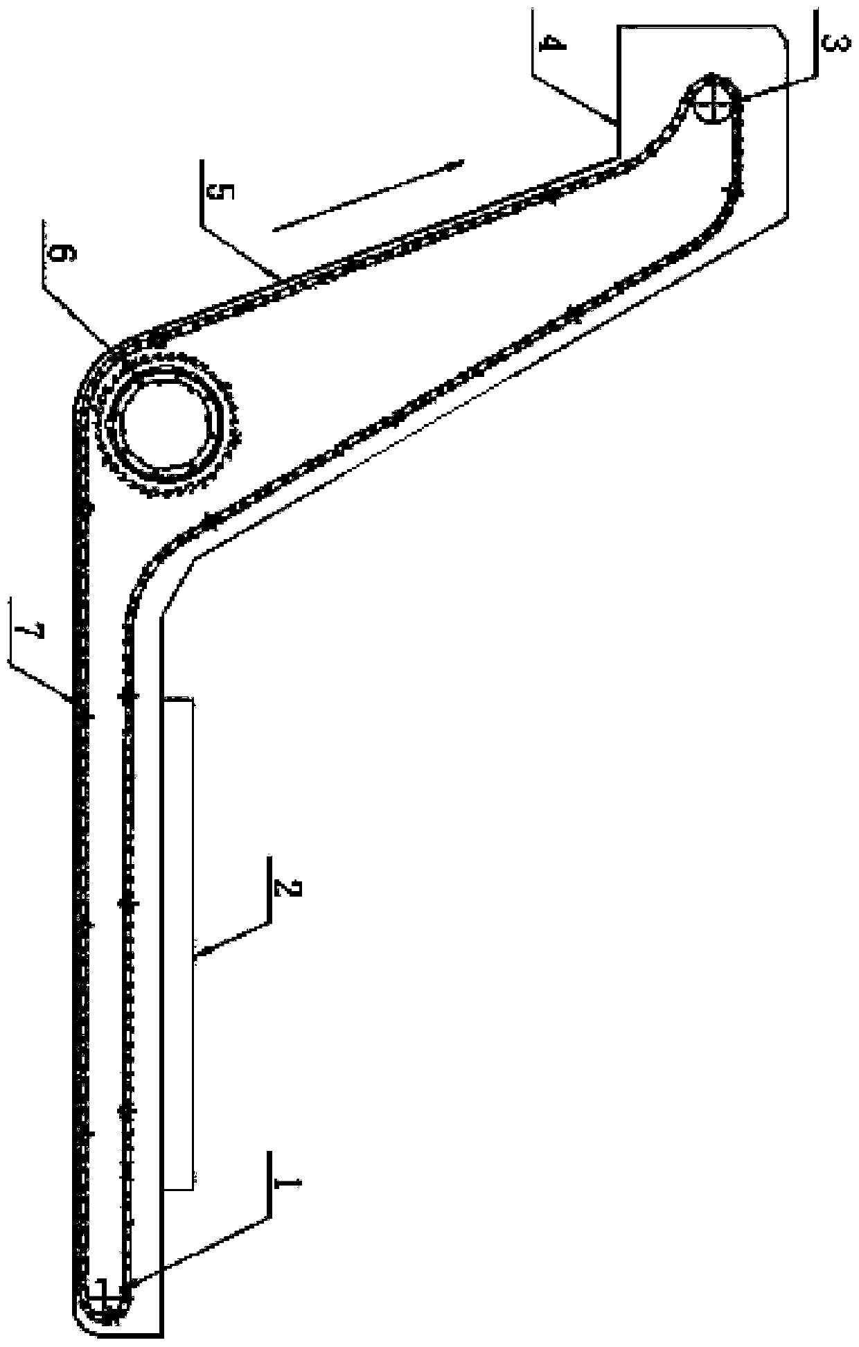
[0030] Such as image 3 with Figure 4As shown, a drum chip removal machine, the structure includes: the chip removal machine main body 5, which is divided into a horizontal section and an inclined rising section, and the chip removal port 2 installed above the horizontal section of the chip removal machine main body is used to remove the chips containing chips The liquid is discharged into the chip conveyor, the tail rotary device 1 is installed at the tail of the horizontal section of the main body of the chip conveyor, the head rotary device 3 is installed at the end of the inclined upward section of the chip conveyor body, and the head rotary device 3 and the tail rotary device The scraper chain belt 7 connected to the device 1, the scraper chain belt 7 is a closed structure, which can be driven around the head slewing device and the tail slewing device, and the roller device 6 is installed at the lower end of the intersection of the horizontal section and the inclined ris...


PUM


Abstract

The invention provides a roller sealing device of a chip removal machine. The roller sealing device is used for solving the technical problems that in the existing technology, end face water sealing,packing and other sealing elements are adopted, elasticity is lost due to ageing, consequently, sealing is invalid, cutting liquid obtained after filtering contains a large number of cutting chippings, a machine tool pipe is blocked, and a cutter is additionally abraded. Main structures of the sealing device comprise a movable ring, a convex ring arranged on the movable ring, a fixed ring and a cover plate, an annular cavity is formed among the above components, a pipe threaded hole is formed in the fixed ring, the pipe threaded hole is connected with a high pressure connector, the high pressure connector communicates with the annular cavity, the sealing function of the sealing device is achieved through the pressure difference and the sealing structure comprehensively, and the problem that the roller device is invalid in sealing is solved. In addition, the invention provide a roller of the chip removal machine and the chip removal machine, and the roller and the chip removal machine both use the structure and the working principle of the above roller sealing device.

Description

technical field [0001] The invention relates to the field of machine tool processing, in particular to a sealing structure for a drum device of a chip removal machine. Background technique [0002] The drum type chip conveyor is used to deal with chips and cutting fluid produced by machine tool processing. Scraper or chain plate is used to separate the chips from the cutting fluid and then discharged. The drum filter device is used to filter the cutting fluid and return it to the machine tool for reuse. separated. At present, the drum-type chip removal machine mostly uses sealing elements such as end face water seals and packing to realize the sealing function. Due to the flow direction of the cutting fluid, there are a lot of chips at the position of the drum, and the wear of end face water seals, packing and other components will inevitably cause wear. In addition, the cutting fluid will also cause the end face water seal, packing and other sealing elements to age and lo...

Claims


Application Information

Patent Timeline
Patent Type & Authority Patents(China)
IPC IPC(8): B23Q11/00B23Q11/10F16J15/40
CPCB23Q11/0042B23Q11/1069F16J15/40
Inventor 何国峰王宁马同堂赵亚宁
Owner NINGXIA KOCEL MACHINE TOOL ACCESSORIES
Why Eureka
Try Eureka