Eureka AIR delivers breakthrough ideas for toughest innovation challenges, trusted by R&D personnel around the world.

Centrifugal equipment for manufacturing cement telephone pole

A technology of cement utility poles and centrifugal equipment, which is applied in the direction of manufacturing tools, non-rotating vibration suppression, ceramic molding machines, etc., can solve the problems of slow speed of cement utility poles, high noise of vibrating rods, and time-consuming, etc., and achieve fast molding speed , saving time, reasonable structure design effect

Inactive Publication Date: 2018-07-27
盐城市新驰工贸有限公司
View PDF0 Cites 3 Cited by
  • Summary
  • Abstract
  • Description
  • Claims
  • Application Information

AI Technical Summary

Problems solved by technology

[0002] Traditional cement utility poles manually add cement and steel bars into the mold, and then manually tamp the cement in the mold with a vibrating rod, and then make it solidify. Manually making cement utility poles is slow, requires a lot of manpower, and takes a lot of time. , and it is easy to scratch the hands. At the same time, the noise of the vibrator is loud when it is working, and the operator who works under the noise for a long time will feel uncomfortable. Cement pole forming device

Method used


Image

  • Centrifugal equipment for manufacturing cement telephone pole
  • Centrifugal equipment for manufacturing cement telephone pole

Examples


Embodiment Construction

[0012] The following will clearly and completely describe the technical solutions in the embodiments of the present invention with reference to the accompanying drawings in the embodiments of the present invention. Obviously, the described embodiments are only some, not all, embodiments of the present invention.

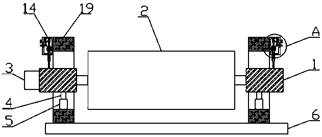
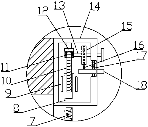
[0013] refer to Figure 1-2 , a centrifugal device for making cement poles, comprising a base 6, the upper end of the base 6 is fixedly connected with two support plates 19, the side walls of the two support plates 19 are provided with hollow chute, and the two hollow chute There are installation blocks 1 inside, the inner wall of the hollow chute is fixedly connected with a buffer device, the upper end of the buffer device is fixedly connected with the lower end of the installation block 1, and the side walls of the two support plates 19 are fixedly connected with a housing 14, the housing The inner wall of 14 is fixedly connected with two limiting blocks 9, and a s...


PUM


Abstract

The invention discloses centrifugal equipment for manufacturing a cement telephone pole. The centrifugal equipment comprises a base; two supporting plates are fixedly connected to the upper end of thebase; a hollow chute is formed in the side wall of each supporting plate and is internally provided with a mounting block; a buffer device is fixedly connected to the inner wall of each hollow chute;the upper end of each buffer device is fixedly connected to the lower end of the corresponding mounting block; a shell is fixedly connected to the side wall of each supporting plate; two limiting blocks are fixedly connected to the inner wall of each shell; a strip plate is movably connected between two adjacent limiting blocks; a first circular cavity is arranged at the upper end of each strip plate and is internally provided with a threaded rod; inside threads which are matched with each threaded rod are formed in the inner wall of the corresponding first circular cavity; and the upper endof each threaded rod is rotationally connected to the internal top of the corresponding shell. The centrifugal equipment provided by the invention has the effects of reasonability in structure design,simpleness in operation, rapidness in formation speed of a cement pole, capability of saving manpower and time and no capability of brushing a hand to hurt.

Description

technical field [0001] The invention relates to the technical field of making cement poles, in particular to a centrifugal device for making cement poles. Background technique [0002] Traditional cement utility poles manually add cement and steel bars into the mold, and then manually tamp the cement in the mold with vibrating rods, and then make it solidify into shape. Manually making cement utility poles is slow, requires a lot of manpower, and takes a lot of time. , and it is easy to scratch the hands. At the same time, the vibrating rod is noisy when it is working, and the operator who works under the noise for a long time will feel uncomfortable. Concrete utility pole forming device. Contents of the invention [0003] The purpose of the present invention is to solve the shortcomings in the prior art, and propose a centrifugal device for making cement utility poles. [0004] In order to achieve the above object, the present invention adopts the following technical so...

Claims


Application Information

Patent Timeline
Patent Type & Authority Applications(China)
IPC IPC(8): B28B21/30F16F15/02
CPCB28B21/30F16F15/02
Inventor 蔡一根
Owner 盐城市新驰工贸有限公司
Why Eureka
Eureka Blog
Learn More