
Capacity-tube-capacity type gas-flow pulsation attenuator of compressor

An air pulsation and compressor technology, applied in the direction of machine/engine, mechanical equipment, variable displacement pump components, etc., can solve the problem of increasing the resistance loss of the capacity-tube-capacity air pulsation attenuator, reducing the economy and reliability of the compressor. performance, poor airflow pulsation attenuation, etc.

Inactive Publication Date: 2018-07-27
QINGDAO UNIV OF SCI & TECH
View PDF0 Cites 0 Cited by
  • Summary
  • Abstract
  • Description
  • Claims
  • Application Information

AI Technical Summary

Problems solved by technology

The air flow pulsation in the pipeline will induce the vibration and noise of the compression system, bring safety hazards, and reduce the economy and reliability of the compressor
Moreover, the severe air flow pulsation in the pipeline will greatly increase the power consumption of the compression system, which violates the demand for energy saving and emission reduction.
[0003] At present, the commonly used devices for reducing air flow pulsation are mainly designed based on the principle of avoiding resonance under the condition of constant speed. Under working conditions, the attenuation effect of airflow pulsation in the pipeline is very poor; by designing the cut-off frequency of the volume-tube-volume airflow pulsation attenuator to fix it at the main excitation frequency at the lowest speed, this attenuator can effectively attenuate The airflow in the pipeline fluctuates at variable speed, but as the speed increases, the flow velocity in the pipeline increases, which will greatly increase the resistance loss of the volume-tube-volume airflow pulsation attenuator

Method used


Image

  • Capacity-tube-capacity type gas-flow pulsation attenuator of compressor
  • Capacity-tube-capacity type gas-flow pulsation attenuator of compressor
  • Capacity-tube-capacity type gas-flow pulsation attenuator of compressor

Examples


Embodiment Construction

[0019] The present invention is described in further detail below in conjunction with accompanying drawing:

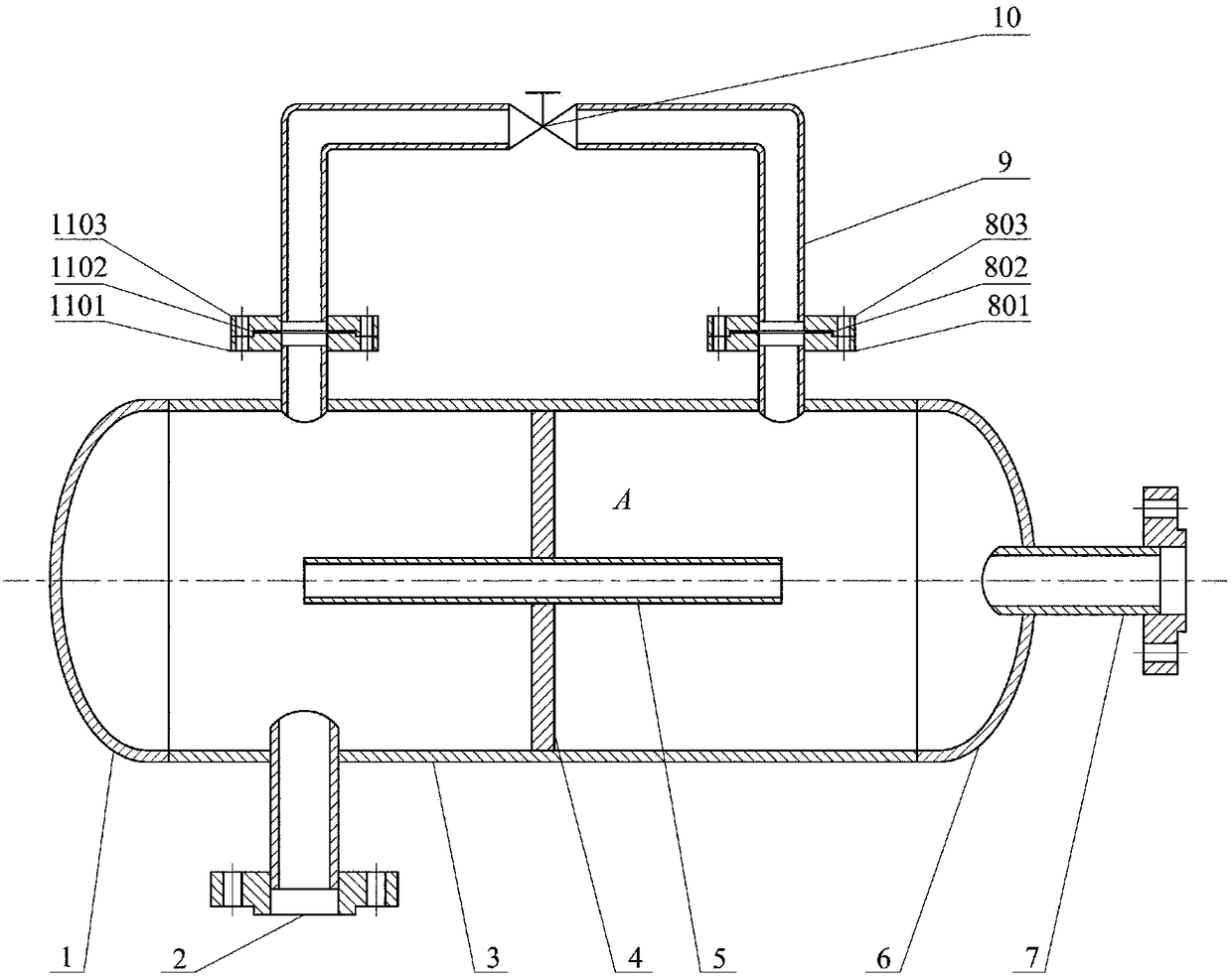
[0020] see picture figure 1 As shown, the compressor capacity-tube-capacity air flow pulsation attenuator proposed by the present invention includes a container shell 3, a head 1, a head 6, an inner throat 5, an outer throat 9 and a circular The partition 4, wherein the container shell 3 is a cavity with two sections of open cylindrical structure, the two ends of the container shell 3 are respectively connected with the left head 1 and the right head 6, the container shell 3 and the left head 1. The right sealing head 6 together forms the container chamber A. The inner wall surface of the container shell 3 is fixed with a coaxial circular partition 4, and a through hole is opened on the circular partition 4, and an inserting throat 5 is coaxially and tightly fixed on the through hole, and the connection method can be threaded connection or welding .

[0021] The out...


PUM


Abstract

The invention discloses a capacity-tube-capacity type gas-flow pulsation attenuator of a compressor. The capacity-tube-capacity type gas-flow pulsation attenuator mainly consists of an accommodating cavity, an interpolated throat tube, an extrapolated throat tube with an adjustable valve opening, and a partition, wherein the attenuator is mounted between the compressor and a pipeline through a flange; the partition is used for dividing the accommodating cavity into two small accommodating cavities; the interpolated throat tube communicates with the extrapolated throat tube for regulating opening of a valve on the extrapolated throat tube, so that cut-off frequency of an acoustic low-pass filter which consists of two small accommodating cavities and a middle connecting throat tube can be changed, and therefore, main excitation of the compressor and gas-flow pulsation wave corresponding to the frequency are greatly reduced, pulsation gas flow in the pipeline tends to be stable, and the problem that a conventional pulsation attenuator only can effectively attenuate gas-flow pulsation in a fixed-rotation-speed compressor pipeline and is poor in pulsation attenuation effect in the variable-rotation-speed compressor pipeline is solved. The capacity-tube-capacity type gas-flow pulsation attenuator can be conveniently mounted at a gas inlet flange and a gas outlet flange of the compressor, and further can be simultaneously used with a Helmholtz resonator or other pulsation attenuators.

Description

technical field [0001] The invention belongs to the field of fluid machinery, and relates to a volume-tube-volume air flow pulsation attenuator, in particular to a volume-tube-volume air flow pulsation attenuator for variable-speed reciprocating compressors. Background technique [0002] As the "heart" equipment for pressurizing and transporting gas, compressors are widely used in petroleum, chemical industry, aerodynamics and other fields, especially reciprocating piston compressors, whose periodic suction and exhaust will stimulate strong vibration in the pipeline system. Air pulsation. The air flow pulsation in the pipeline will induce the vibration and noise of the compression system, bring safety hazards, and reduce the economy and reliability of the compressor. Moreover, the severe air flow pulsation in the pipeline will greatly increase the power consumption of the compression system, which violates the demand for energy saving and emission reduction. [0003] At pr...

Claims


Application Information

Patent Timeline
IPC IPC(8): F04B39/14F04B39/00
CPCF04B39/00F04B39/0055F04B39/14
Inventor 刘展陈志凯
Owner QINGDAO UNIV OF SCI & TECH
Learn More