An adsorption pressurized recovery system for volatile organic vapors in oil and gas

A volatile organic compound and recovery system technology, applied in gas treatment, steam condensation, membrane technology, etc., can solve problems such as poor dynamic regulation, useless work, compressor flash explosion, etc., to ensure continuity and coordination, and avoid useless work loss , Reduce the effect of air pulsation

Active Publication Date: 2018-05-25
ANHUI KEHAI COMPRESSOR MFG
View PDF7 Cites 0 Cited by
  • Summary
  • Abstract
  • Description
  • Claims
  • Application Information

AI Technical Summary

Problems solved by technology

[0010] 1. The normal-temperature gasoline spraying process as an absorbent will inevitably produce a certain amount of evaporation, and this part of the evaporated oil and gas will merge with the oil and gas in the oil depot and be sent to the inlet of the activated carbon tank, which will increase the adsorption load, resulting in a large activated carbon tank and a larger vacuum pump configuration.
[0011] 2. The one-time investment cost of equipment is large, and the floor area is large
[0014] 1. Regardless of the pressurization process or the refrigeration process, most of the compression power consumption and refrigeration power consumption are occupied by the air that accounts for the majority of the oil and gas components, resulting in a large amount of useless work and high energy consumption
[0015] 2. The device adopts an open process, and the dynamic adjustment is poor. When the device is initially operated and the concentration of oil and gas changes, it is difficult for the refrigeration system to achieve the ideal condensation effect at once, which will cause the concentration of organic matter in the exhaust gas to exceed the standard
[0016] 3. The explosive concentration range of oil and gas is roughly 0.6% to 7%. When the concentration of organic matter entering the gas booster is close to this range, the operation of the compressor may cause flash explosion.

Method used


Image

  • An adsorption pressurized recovery system for volatile organic vapors in oil and gas

Examples


Embodiment Construction

[0035] In order to make the object, technical solution and advantages of the present invention clearer, the present invention will be further described in detail below in conjunction with the accompanying drawings and embodiments. It should be understood that the specific embodiments described here are only used to explain the present invention, not to limit the present invention.

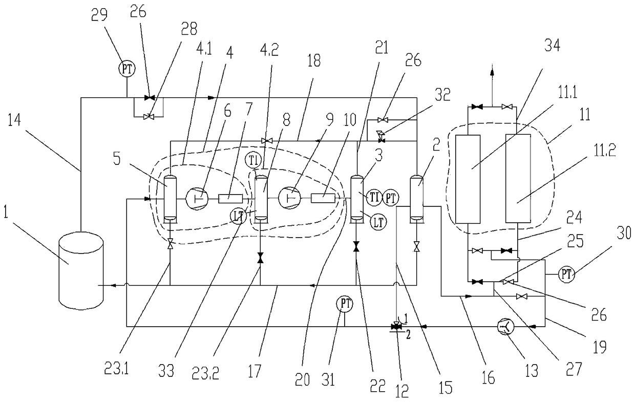
[0036] Such as figure 1 As shown, the present invention provides an adsorption pressurized recovery system for volatile organic compound vapor in oil and gas, including an oil storage tank 1, which is a prior art, and the oil storage tank 1 passes through a first pipeline 14 Connect the air inlet of the condensate separation tank 2, the condensate separation tank 2 also adopts the prior art, an air outlet of the condensate separation tank 2 is connected to the liquefaction device 4 through the second pipeline 15, the condensate separation The other gas outlet of the tank 2 is connected to the adso...


PUM


Abstract

The invention discloses a system for adsorption and pressure-boosting recovery of volatile organic compound steam in oil gas. The system comprises an oil storage tank, wherein the oil storage tank is connected with the gas inlet of a condensate separation tank through a first pipeline; the two gas outlets of the condensate separation tank are connected with a liquefaction device and an adsorption tank through a second pipeline and a third pipeline respectively; the liquid outlet of the condensate separation tank is connected with an oil storage tank through a fourth pipeline; the liquefaction device is connected with the first pipeline through a fifth pipeline; the adsorption tank is connected with the liquefaction device through a sixth pipeline; a vacuum pump is arranged on the sixth pipeline; the liquid outlet of the liquefaction device is connected with the fourth pipeline through a seventh pipeline; the liquefaction device is connected with the gas inlet of a liquid separation tank through an eighth pipeline; the gas outlet of the liquid separation tank is connected with the fifth pipeline through a ninth pipeline; the liquid outlet of the liquid separation tank is connected with the fourth pipeline through a tenth pipeline. The system has the advantages of adopting such a technological mode that discharged air is firstly adsorbed, and being simple in technology, low in investment cost, and high in safety, and a liquid recovered oil product can be visually observed.

Description

technical field [0001] The invention relates to the technical field of oil gas recovery, in particular to an adsorption pressurized recovery system for volatile organic compound vapor in oil gas. Background technique [0002] In the supply, sale, storage and transportation of gasoline, there is a situation that high-concentration gasoline vapor is discharged into the atmosphere, which seriously pollutes the atmospheric environment and endangers people's health. Taking an oil depot with a loading capacity of 200,000 tons per year as an example, more than 500 tons of gasoline are transferred every day, and the operation time is about 3 hours, and the gasoline vapor generated by it reaches nearly 1,000m 3 , which contains nearly 1 ton of gasoline. In order to recover this part of gasoline vapor, absorption method, adsorption method, condensation method, membrane separation method and their combined process methods are commonly used to recover the oil gas emitted by the evapora...

Claims


Application Information

Patent Timeline
Patent Type & Authority Patents(China)
IPC IPC(8): B01D53/04B01D53/00B01D5/00
CPCB01D53/002B01D53/0407B01D2257/708B01D2258/02
Inventor 吴狄
Owner ANHUI KEHAI COMPRESSOR MFG
Why Eureka
Try Eureka