Ruler and instrument integrated installing frame for leveling

A technology of leveling and mounting brackets, which is applied in the direction of measuring devices, height/level measuring, instruments, etc., can solve problems such as inoperability, damaged leveling rods, time-consuming and labor-intensive combined operations, etc., to solve practical operability problems and prolong service life , to ensure the overall effect

Pending Publication Date: 2018-07-27
大连晶硕机械有限公司
View PDF12 Cites 1 Cited by
  • Summary
  • Abstract
  • Description
  • Claims
  • Application Information

AI Technical Summary

Problems solved by technology

Traditional leveling devices and corresponding operating methods have the following disadvantages: (1) Three-point configuration, asynchronous observation, and low measurement efficiency
Because it takes a lot of energy and time for the surveyors to realize the reasonable configuration of the positions between the three points of the leveling instrument and the leveling rod in a complex terrain environment, and at the same time, the asynchronous observation of readings according to the scales respectively increases the observation time, which affects the In addition, when encountering complex terrain environments such as steep slopes, potholes, ponds, ditches, ravines, rivers, and mountainous areas, it is often impossible to set up the level in the middle of the two leveling rods, resulting in the failure of leveling. implement
(2) Single observation system, low measurement reliability
However, the above-mentioned patent application still has the following deficiencies: (1) The tripod, the leveling rod and the auxiliary ruler pad are set separately. After moving the station, they all need to be combined before leveling. Moreover, it will also affect the accuracy of continuous observation, and even damage the leveling rod during the combination process; (2) When using a three-legged tripod, it will form a four-point landing with the leveling rod, which is difficult to balance and stably place; when the ground height difference is large, After raising or lowering the height of the height signal detector (level), the surveyor cannot aim and focus through the eyepiece due to physical factors; after the tripod is installed, the ruler cannot rotate relative to the tripod (ground), straighten and aim. The steps are difficult to coordinate and cannot work
However, during the development and practice of the composite level, it was found that the patent has the following deficiencies: (1) Since the leveling rod of the composite level is generally 3 to 5 meters, in order to carry, transport and store, other units (altitude measuring device, Observation handbook, auxiliary bracket or tripod, level and auxiliary ruler pad) are separated from the leveling staff and reinstalled again when in use
On the one hand, all parts are in a scattered state when disassembled and separated from the leveling staff, which is inconvenient to classify, store and carry; Disassembly, installation and fixing will continue to squeeze and wear the leveling rod, which will directly affect the service life and observation accuracy of the composite leveling instrument (2) The direct connection between the altimeter and the leveling rod will cause the observation height to be unstable; (3) The ruler pad and the leveling The connection design of the scale is unreasonable, which cannot meet the requirements of the compound level to measure the i angle; (4) The connection design of the electronic hand book and the L-shaped level and the level is unreasonable, which is inconvenient to disassemble and easy to wear; (5) Caster wheel design Unreasonable, not only affects the stable placement of the tripod but also causes inconvenience in movement
All in all, from the perspective of surveying, mechanics, and ergonomics, the above-mentioned patent applications cannot meet the practical operability requirements of man-machine integration in leveling measurement

Method used


Image

  • Ruler and instrument integrated installing frame for leveling
  • Ruler and instrument integrated installing frame for leveling
  • Ruler and instrument integrated installing frame for leveling

Examples


Embodiment Construction

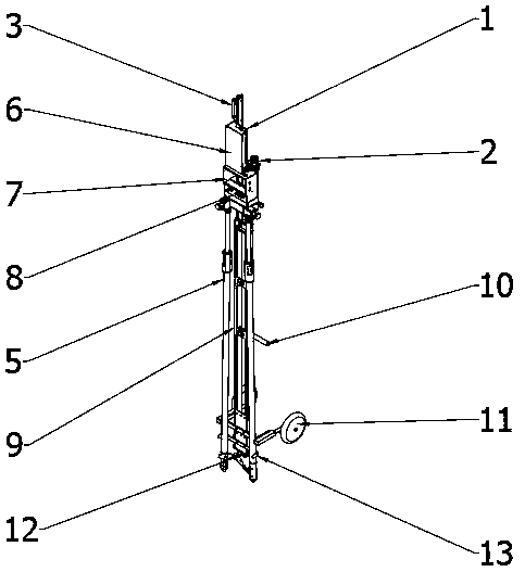
[0020] Examples of the present invention figure 1 Shown: There is a vertical long ruler base 1 made of aluminum alloy and other materials. 1 has a fixture for fixing the leveling staff. The top of the ruler base 1 is fixed with a level installation base 2 and a drag handle 3, the middle part of the ruler base 1 is rotationally connected with the auxiliary tripod 5 through a vertical rotating shaft 4, and the ruler base 1 above the rotating shaft 4 is provided with a battery compartment 6, an electronic hand The book cabin 7 and the L-shaped leveler cabin 8 are provided with a vertical handle 9 and a horizontal handle 10 on the ruler base 1 below the rotating shaft 4, and the lower part of the ruler base 1 is provided with a mobile caster 11 and a foot pad installation base 12. For the convenience of portability, a limit frame 13 for limiting the feet of the auxiliary tripod 5 can be set at the bottom of the ruler base 1 .

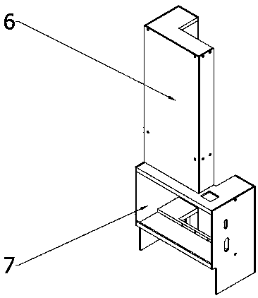
[0021] The shape and structure of the battery compa...


PUM


Abstract

The invention discloses a ruler and instrument integrated installing frame for leveling, wherein the ruler and instrument integrated installing frame is simple and convenient to operate and capable ofimproving the installing efficiency and enhancing practicability. A vertical long-strip-shaped ruler base (1) is arranged, and a level instrument installing base (2) and a dragging handle (3) are fixed to the top end of the ruler base (1). The middle portion of the ruler base (1) is rotationally connected with an auxiliary foot stand (5) through a vertical rotation shaft (4). The part, above therotation shaft (4), of the ruler base (1) is provided with a battery bin (6), an electronic handbook bin (7) and an L-shaped level device bin (8), and the part, below the rotation shaft (4), of the ruler base (1) is provided with a vertical handle (9) and a transverse handle (10). Movable trundles (11), a limiting frame (12) and a ruler pad installing base (13) are arranged at the lower portion ofthe ruler base (1).

Description

technical field [0001] The invention belongs to the technical field of geodetic and engineering surveying, and in particular relates to an integrated installation frame for a ruler and instrument for leveling that is easy to operate, improves installation efficiency, and enhances practicability. Background technique [0002] The traditional leveling device is composed of a leveling instrument and two leveling rods. When measuring, first place the two leveling rods on the ground at points A and B respectively, and then set the leveling instrument at the middle position of the two points A and B. In order to ensure the measurement accuracy, the horizontal distance between the leveling device and the two leveling rods is generally required. Equal or approximately equal. Use the horizontal line of sight of the leveling instrument to read the elevation values ​​of the two leveling rods respectively. The difference between the measured elevation values ​​is the level difference b...

Claims


Application Information

Patent Timeline
Patent Type & Authority Applications(China)
IPC IPC(8): F16M11/04F16M11/16F16M11/20G01C5/00
CPCF16M11/04F16M11/16F16M11/20G01C5/00
Inventor 吴长举吴硕孟强刘雁春
Owner 大连晶硕机械有限公司
Why Eureka
Try Eureka