
Indoor visible light positioning method and apparatus

A positioning method and visible light technology, applied in the direction of measuring devices, instruments, and utilizing re-radiation, can solve the problems of unable to locate the lighting source and require high distribution density of the light source, and achieve the effect of improving efficiency and positioning efficiency

Active Publication Date: 2018-07-27
CHINA ACADEMY OF ELECTRONICS & INFORMATION TECH OF CETC
View PDF9 Cites 11 Cited by
  • Summary
  • Abstract
  • Description
  • Claims
  • Application Information

AI Technical Summary

Problems solved by technology

[0004] However, most of the current visible light positioning methods require the receiving end to collect information from multiple target lighting sources at the same time, and cannot perform positioning based on a single target lighting source. high

Method used


Image

  • Indoor visible light positioning method and apparatus
  • Indoor visible light positioning method and apparatus
  • Indoor visible light positioning method and apparatus

Examples


Embodiment Construction

[0028] It should be understood that the specific embodiments described here are only used to explain the present invention, not to limit the present invention.

[0029] In the following description, use of suffixes such as 'module', 'part' or 'unit' for denoting elements is only for facilitating description of the present invention and has no specific meaning by itself. Therefore, 'module', 'part' or 'unit' may be used in combination.

[0030] In order to facilitate the understanding of the embodiments of the present invention, the implementation process of the present invention will be described in detail below through several specific examples.

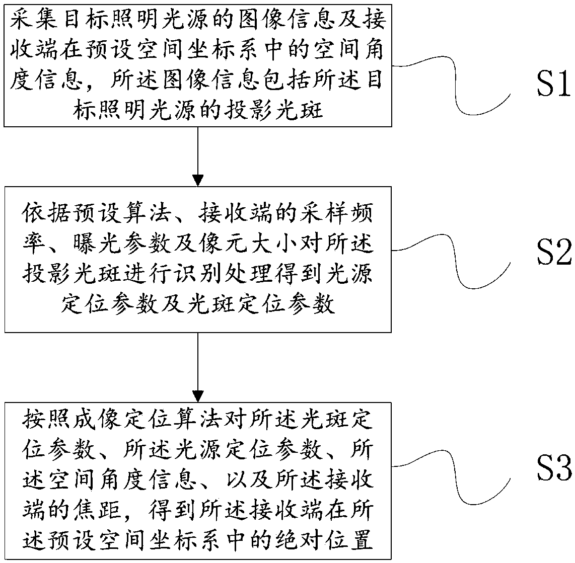
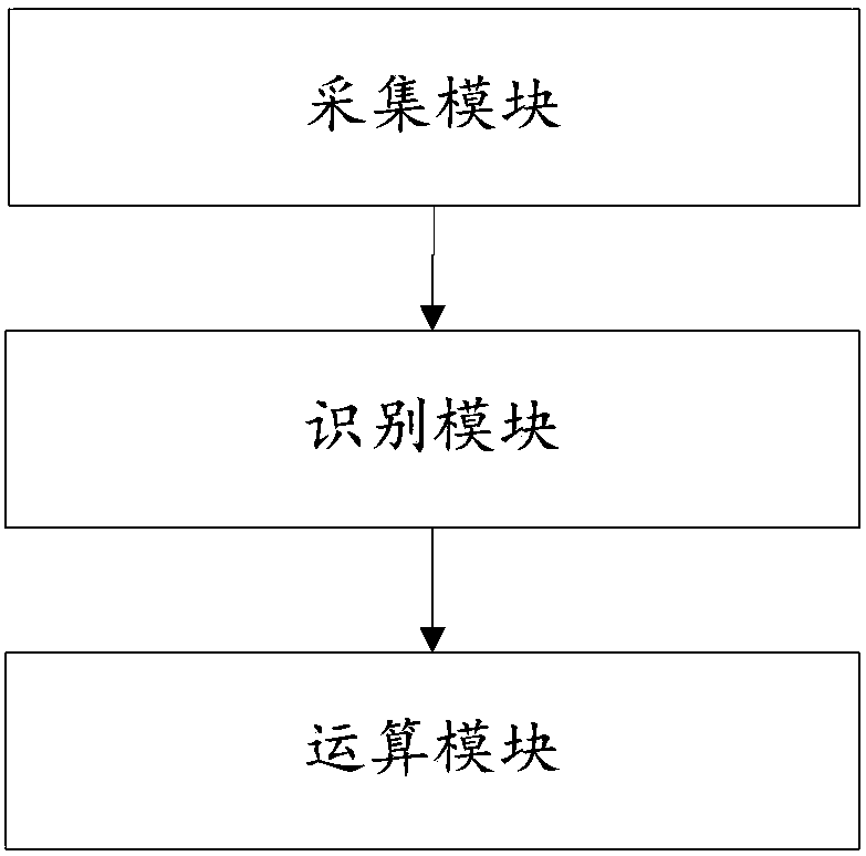
[0031] The first embodiment of the present invention provides an indoor visible light positioning method. Based on the receiving end, the method includes:

[0032] Collect the image information of the target lighting source and the spatial angle information of the receiving end in the preset space coordinate system, the image informa...


PUM


Abstract

The invention discloses an indoor visible light positioning method and apparatus. The indoor visible light positioning method comprises the following steps: collecting the image information of a target illumination light source and the spatial angle information of a receiving end in a preset space coordinate system, wherein the image information comprises the projection spot of the target illumination source; identifying the projection spot based on a preset algorithm, the sampling frequency of the receiving end, exposure parameters and a pixel size so as to obtain light source positioning parameters and spot positioning parameters; and carrying out calculation by using imaging positioning algorithms based on the spot positioning parameters, the light source positioning parameters, the spatial angle information and the focal length of the receiving end so as to obtain the absolute position of the receiving end in the preset space coordinate system. The method and apparatus of the invention can acquire the spot positioning parameters and the light source positioning parameters only through the spot of the image information of one illumination source during the positioning of the receiving end, so the absolute position of the receiving end in the preset space coordinate system is acquired in virtue of the spot positioning parameters and the light source positioning parameters.

Description

technical field [0001] The invention relates to an indoor visible light positioning technology with integrated lighting, in particular to an indoor visible light positioning method and device. Background technique [0002] In recent years, with the continuous development of smart cities and location-based services, demands and applications related to indoor positioning have emerged. Due to the poor positioning effect of traditional satellite signal-based positioning systems (GPS, Beidou, etc.) in indoor environments, they cannot be used effectively. Indoor positioning methods and systems based on principles such as inertial navigation. These positioning methods have not been popularized due to the limitations of layout cost, positioning accuracy and system adaptability. With the advancement of solid-state light source technology, solid-state light sources represented by LEDs have gradually become the mainstream of the lighting market due to their advantages such as high lu...

Claims


Application Information

Patent Timeline
IPC IPC(8): G01C21/20G01S11/12
CPCG01C21/206G01S11/12
Inventor 蔺博黄河清
Owner CHINA ACADEMY OF ELECTRONICS & INFORMATION TECH OF CETC
Learn More