
Machine-soil acting force soil groove testing and detecting device and method thereof

A detection device and force technology, which is applied in the field of agricultural machinery, can solve the problems of low test accuracy of machine advance speed and inability to simulate the working conditions of paddy field soil, etc., and achieve the effect of compact device structure and high measurement accuracy

Active Publication Date: 2018-07-27
ZHEJIANG UNIV
View PDF8 Cites 8 Cited by
  • Summary
  • Abstract
  • Description
  • Claims
  • Application Information

AI Technical Summary

Problems solved by technology

[0003] The purpose of the present invention is to overcome the low precision of traditional soil tank test bench equipment-soil action force and equipment forward speed test, and it can only be used for dryland soil operation equipment performance test, and cannot simulate complex and adjustable paddy field soil operation conditions, and cannot be used Due to the shortcomings of machine tool-soil action force and operation performance index measurement under different paddy field conditions, the present invention provides a machine tool-soil action force soil tank test detection device and method thereof, by filling the soil tank with the required type of soil and Pretreatment is carried out to meet the field conditions of dry field machine tool-soil interaction force test. By filling the soil tank with the required type of soil and performing pretreatment and water filling to simulate paddy field operating conditions such as different water content and surface water depth, the machine tool-soil interaction The force and machine forward speed are directly measured and recorded synchronously, providing a detection device for the tool-soil force measurement and machine performance testing in different dry land and paddy field conditions

Method used


Image

  • Machine-soil acting force soil groove testing and detecting device and method thereof
  • Machine-soil acting force soil groove testing and detecting device and method thereof
  • Machine-soil acting force soil groove testing and detecting device and method thereof

Examples


Embodiment Construction

[0031] The present invention will be further described below in conjunction with the accompanying drawings and embodiments, and the technical features in each embodiment can be combined with each other without conflict, which does not constitute a limitation.

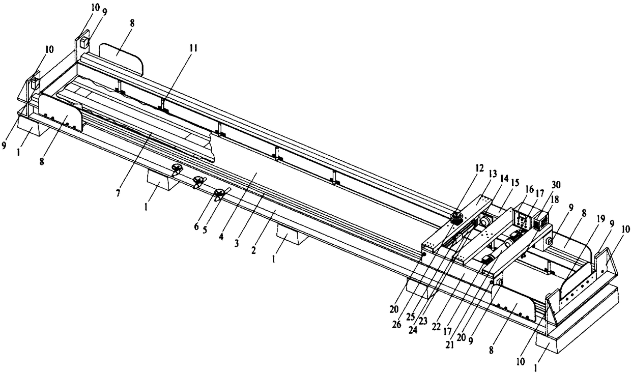
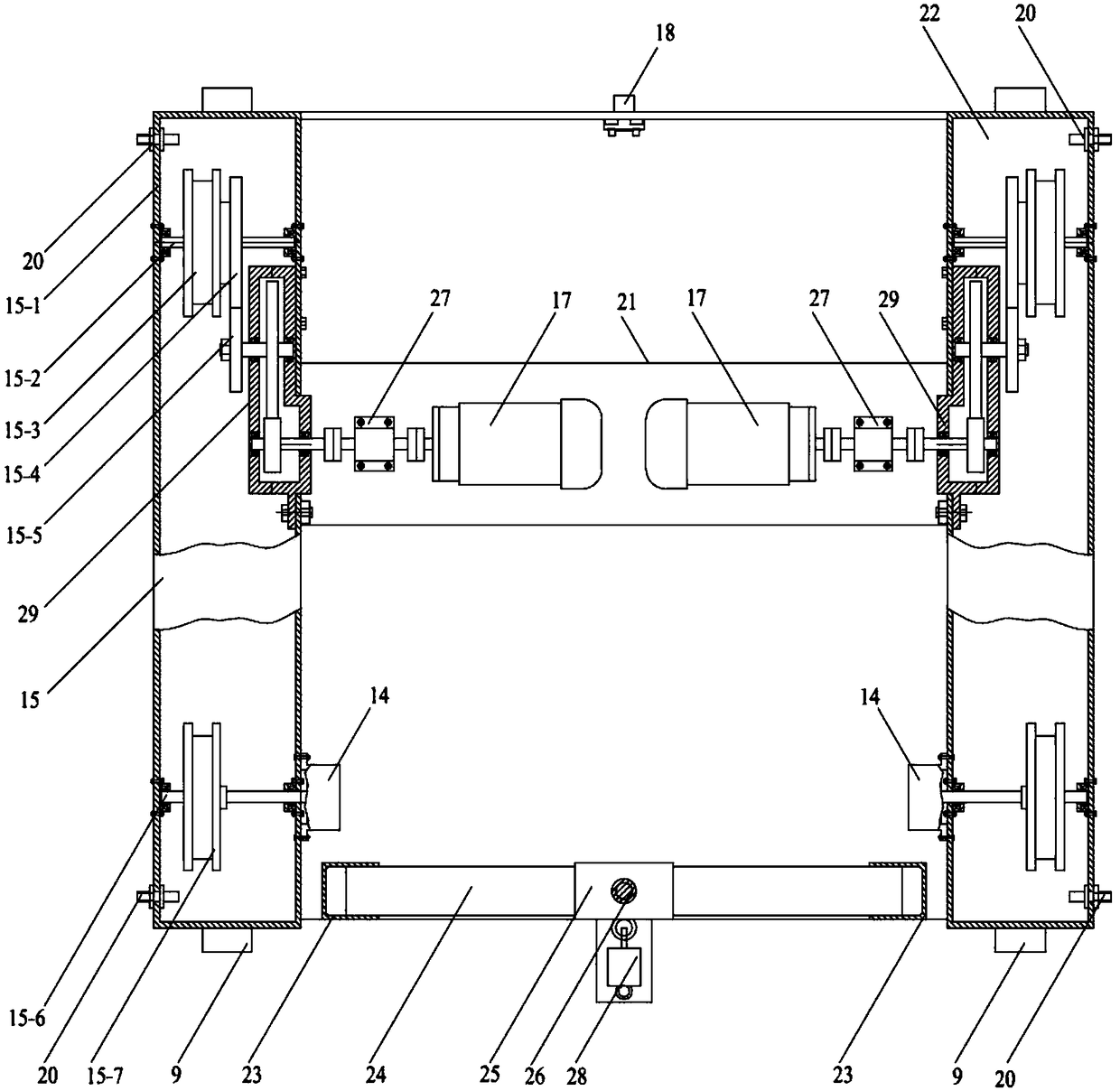
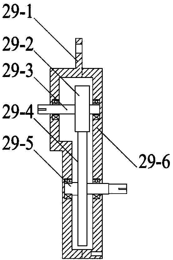
[0032] Such as figure 1 , figure 2 , image 3 , Figure 4 As shown, the device-soil action force soil tank test detection device is characterized in that it includes a soil tank, a traction assembly, a control assembly, and a data acquisition assembly.

[0033] The soil tank includes base 1, tank box 2, track 3, inner tank 4, drain pipe 5, valve 6, longitudinal bottom beam 7, buffer block 9, limit pile 10, contour detection pipe 11, and multi-support base 1 Horizontally uniformly fixed on the ground, the upper surface of each base 1 is on the same level, the tank box 2 is a rectangular frame, the bottom of the tank box 2 is fixed on multiple bases 1, and multiple vertical bottom beams 7 are longitudinally fixed on t...


PUM


Abstract

The invention discloses a machine-soil acting force soil groove testing and detecting device and a method thereof. The device comprises a soil groove, a traction assembly, a control assembly and a data acquisition assembly, the traction assembly is arranged on a track of the soil groove through a track wheel, by filling the soil groove with soil of the testing requirement type and conducting pretreatment, upland field operating conditions can be simulated, by changing the paddy field soil type, the water content, the surface layer water depth, the standing time and the like in the soil groove,all paddy field environment conditions can be simulated, the control assembly is utilized to control the traction assembly to conduct speed stepless adjustment for forwarding and retreating, the dataacquisition assembly is utilized to synchronously record the machine-soil acting force, and the machine forwarding speed and the traction torque. The device is compact in structure, the working process is automatically controlled, the testing precision is high, requirements of an agricultural machine and power source key parts thereof for soil acting force resistance testing are met, and the device and the method thereof can also be used for detecting and testing the machine performance.

Description

technical field [0001] The invention belongs to the field of agricultural machinery, and relates to a soil tank test and detection device for detecting the machine-tool-soil interaction force under different working conditions. Background technique [0002] The interaction between agricultural machinery and its power devices and soil is very complex, and its research has always been the basis for the design and optimization of related machinery. The current research methods are mainly field experiments and laboratory soil tank experiments. In the field test, the soil conditions are not uniform and difficult to determine accurately, the land is uneven, the test parameters are poorly adjustable, and it is rarely used in the measurement of the machine tool-soil interaction force; the traditional laboratory soil tank test device is basically based on the machine tool dry land The operation performance is designed for the goal, the device is basically carried out in the tunnel, t...

Claims


Application Information

Patent Timeline
IPC IPC(8): G01M99/00
Inventor 王永维何焯亮郝一枫王俊曹明
Owner ZHEJIANG UNIV
Learn More