Bias scanning mode industrial CT system rotating table rotating center calibration method

A scanning mode and rotation center technology, which is applied in the field of calibration of the rotation center of the turntable of the industrial CT system in the offset scanning mode, can solve problems such as difficult to achieve fast and accurate calibration of the projection position of the rotation center, shorten the running time of the algorithm, improve the detection efficiency, The effect is simple and convenient

Active Publication Date: 2018-07-27
BEIHANG UNIV
View PDF5 Cites 7 Cited by
  • Summary
  • Abstract
  • Description
  • Claims
  • Application Information

AI Technical Summary

Problems solved by technology

And because the sinogram obtained by the offset scanning mode is unilaterally truncated, it is difficult to achieve fast and accurate calibration of the projection position of the rotation center by conventional methods

Method used


Image

  • Bias scanning mode industrial CT system rotating table rotating center calibration method
  • Bias scanning mode industrial CT system rotating table rotating center calibration method
  • Bias scanning mode industrial CT system rotating table rotating center calibration method

Examples


Embodiment Construction

[0034] The specific implementation manners of the present invention will be further described in detail below in conjunction with the accompanying drawings and embodiments. The following examples are used to illustrate the present invention, but are not intended to limit the scope of the present invention.

[0035] Before describing the method for calibrating the rotation center of the turntable of the industrial CT system in the offset scanning mode provided by the present invention, the standard fan beam scanning mode will be explained first.

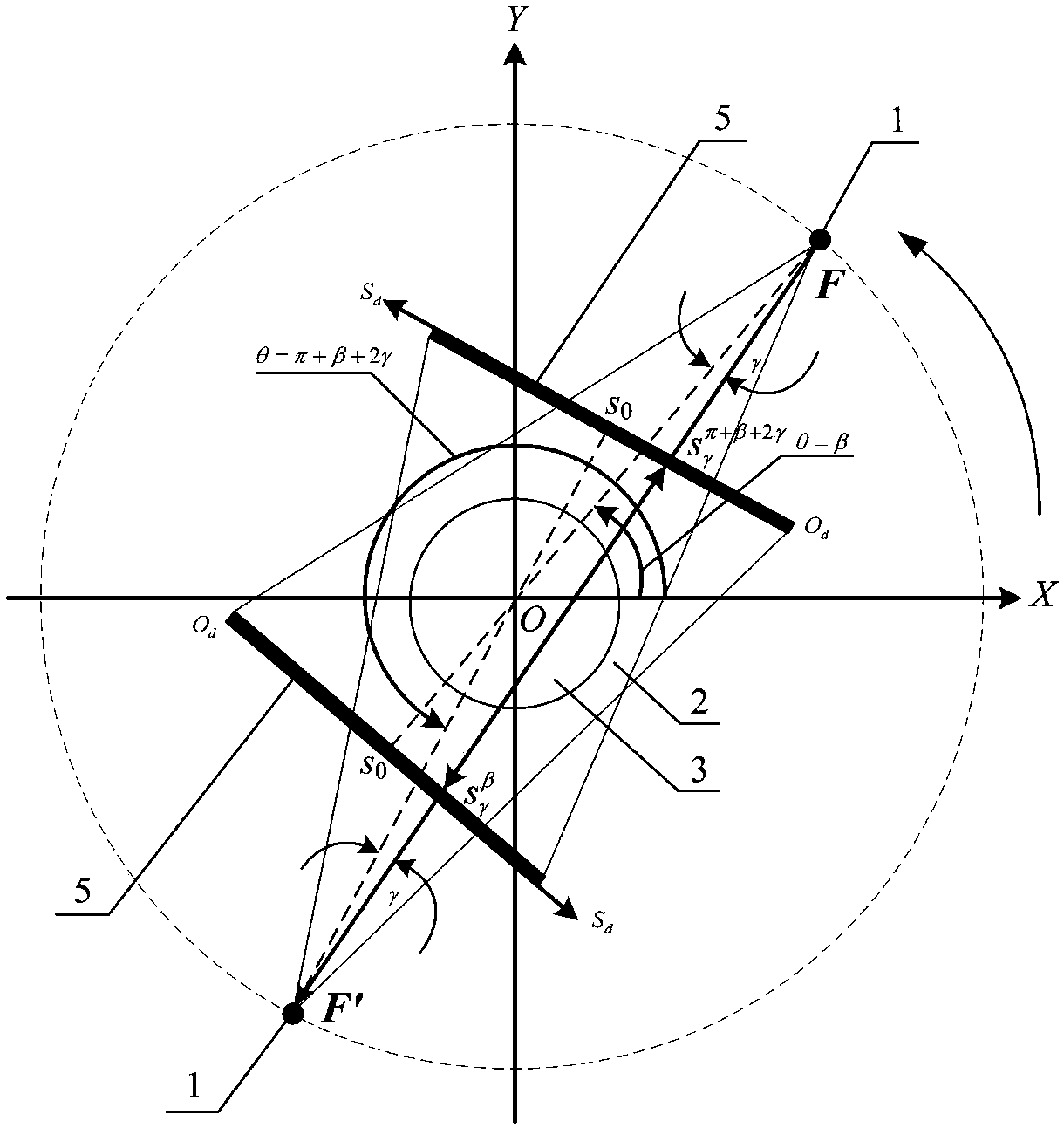
[0036] image 3 is the equivalent schematic diagram of the standard fan beam scanning mode in the prior art, such as image 3 As shown, during standard fan beam scanning, when the line connecting the radiation source 1 and the rotation center O is perpendicular to the detector 5, the radiation source 1 and the detector remain stationary, and the scanned slice rotates 360° around the rotation axis. This scanning process is equivalent...


PUM


Abstract

The invention provides a bias scanning mode industrial CT system rotating table rotating center calibration method, which comprises the following steps of according to the initial step length, uniformly installing a plurality of detector nodes at a real detector; obtaining the corresponding relationship of the detector unit on a virtual detector corresponding to the current node on the real detector and the detector unit on the real detector; obtaining a test sinusoidal chart according to the original sinusoidal chart and the corresponding relationship; calculating the center estimation valuecorresponding to the test sinusoidal chart; regulating the current node according to the preset step length increment; repeating the steps until the distance between the current node and the left endpoint of the real detector is not smaller than a preset threshold value after the regulation; using the detector node corresponding to the smallest center estimation value as a rotating center. The problem of the bias scanning mode rotating table rotating center calibration is solved; in addition, a special calibration model body is not needed by the calibration method; the method is simple and convenient; by setting the solving step length in the solving process, the solving precision of the provided method is controllable.

Description

technical field [0001] The present invention relates to the field of CT technology, and more particularly, to a method for calibrating the rotation center of a turntable of an industrial CT system in an offset scan mode. Background technique [0002] At present, CT (Computed Tomography, computerized tomography) is a non-destructive testing method that uses the projection information of objects under different viewing angles, combined with image reconstruction algorithms, to obtain internal quality status and structural information of objects. The marine field has a wide range of applications. [0003] figure 1 It is a schematic diagram of fan-beam CT offset scanning mode in the prior art, figure 2 It is a schematic diagram of the fan-beam CT offset scanning mode in the prior art, such as figure 1 with figure 2 As shown, when performing standard fan beam scanning, the radiation source 1 emits fan beam rays 2, and the scanned slice 3 rotates around the rotation center 4 ...

Claims


Application Information

Patent Timeline
Patent Type & Authority Applications(China)
IPC IPC(8): G01N23/04
Inventor 杨民林强孟凡勇孙亮宋鑫冯健张玉成
Owner BEIHANG UNIV
Why Eureka
Try Eureka