Supercharge Your Innovation With Domain-Expert AI Agents!

Current probe

A current probe and current needle technology, applied in the field of current probes, can solve problems such as puncture, uneven needle surface, abnormal needle burning, etc.

Pending Publication Date: 2018-07-27
珠海创宝电子科技有限公司
View PDF1 Cites 5 Cited by
  • Summary
  • Abstract
  • Description
  • Claims
  • Application Information

AI Technical Summary

Problems solved by technology

However, in the process of pressing the current terminal to the tab, the tapered needle point 112 is used to directly pierce the surface of the tab, which may seriously scratch the tab. After long-term use, the needle surface is uneven and burns easily needle abnormality

Method used


Image

  • Current probe
  • Current probe
  • Current probe

Examples


Embodiment 1

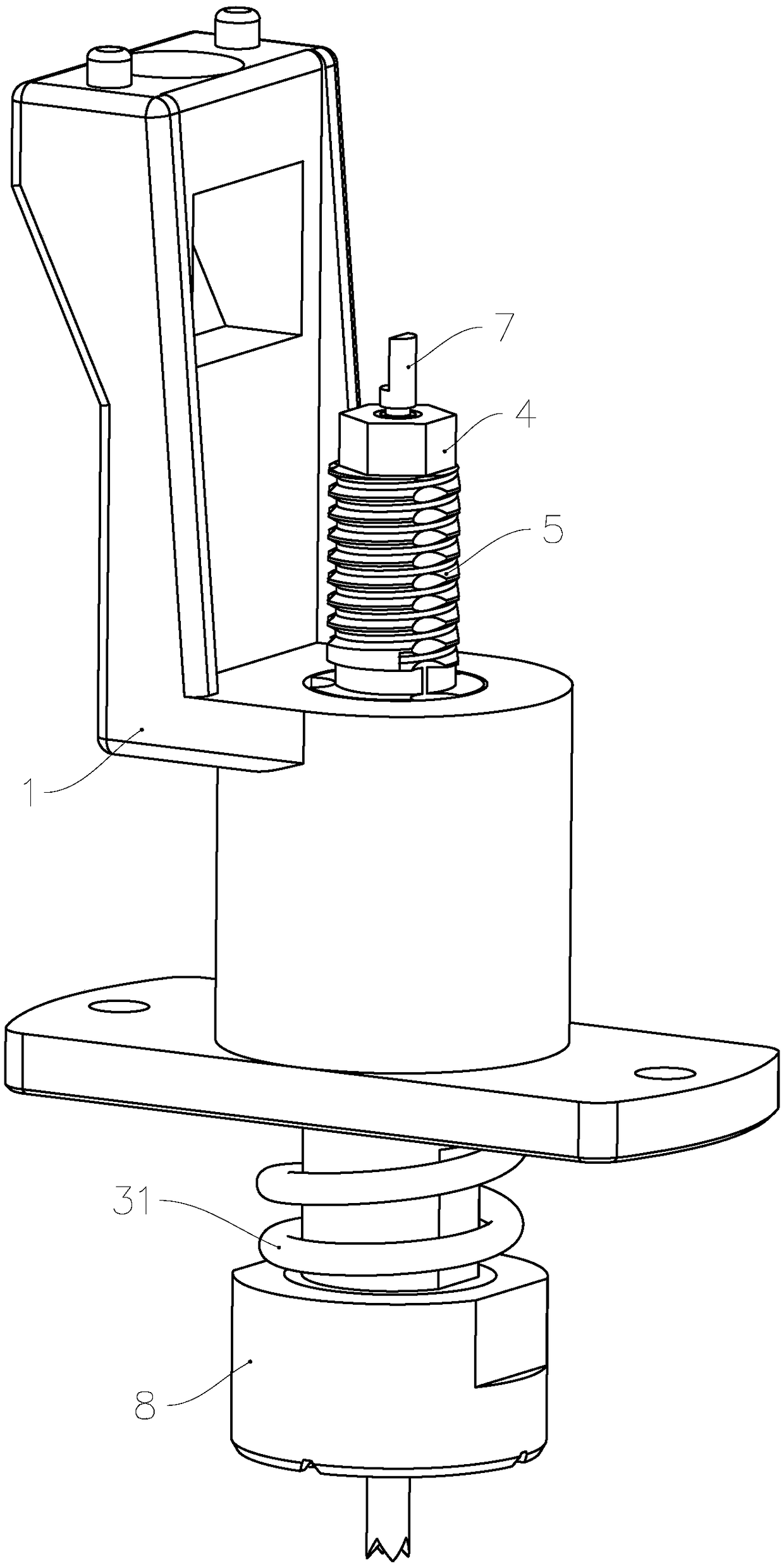
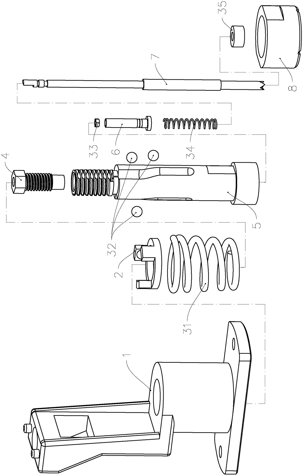
[0034] see Figure 1 to Figure 12 , the current probe of the present invention includes a mount 1 and a ball mount 2 mounted on the mount 1, a second compression spring 31, three balls 32, a first compression spring 34, a lower insulating ring 35, an upper insulating ring 4. Current needle tube and sampling needle rod.

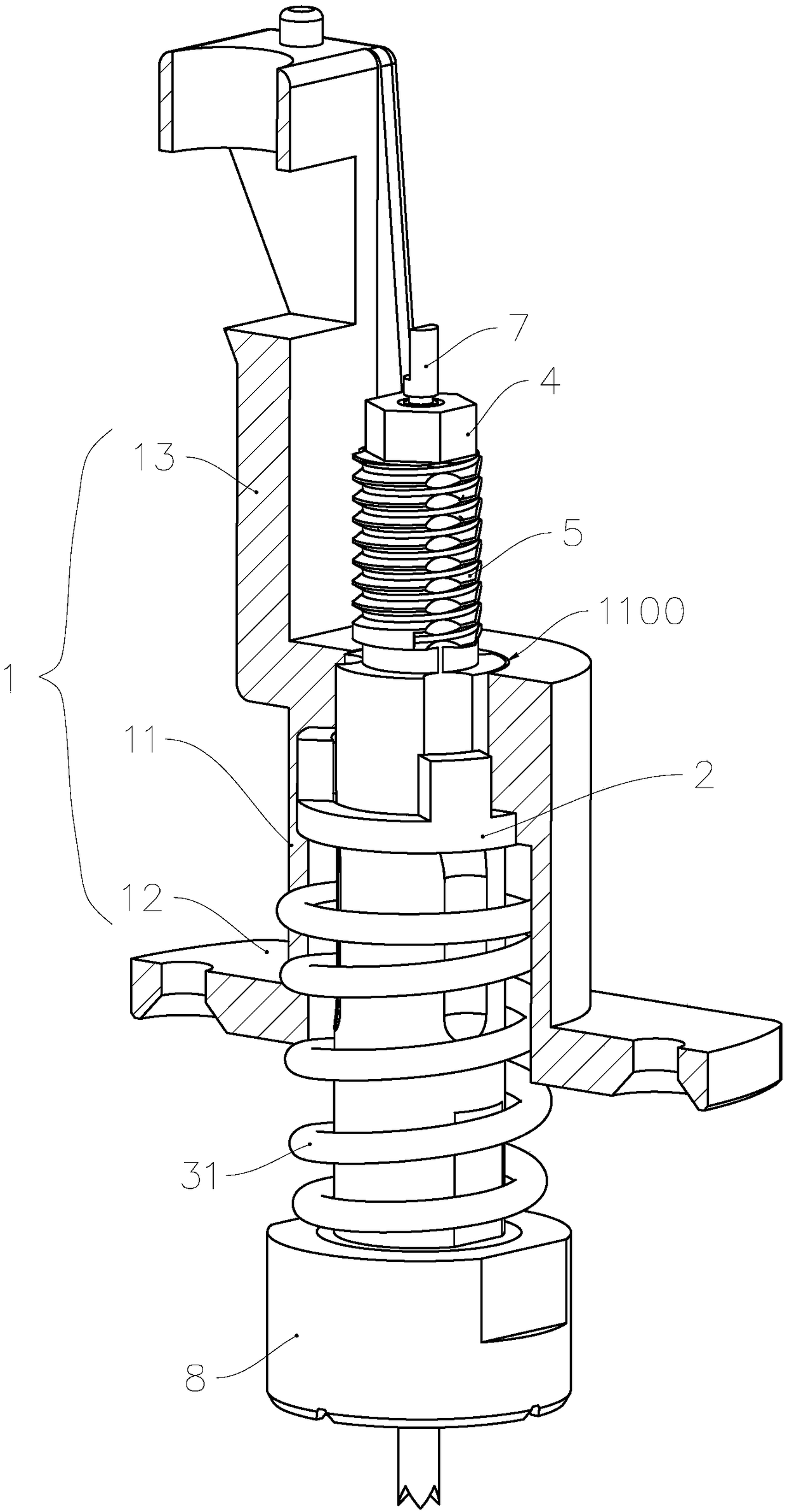
[0035] Such as image 3 and Figure 4 As shown, the mounting base 1 includes a sleeve portion 11, a mounting lug 12 fixed on the lower end of the sleeve portion 11, and an anti-outer seat fixed on the upper end of the sleeve portion 11 and made in an integrated manner. The wiring fixing column 13 for cable traction; the top of the wiring fixing column 13 is connected with the base pipe 5 by a nut with a flexible connection wire; the wiring fixing column 13 deviates outward from the axial direction of the casing part 11 to avoid the current needle tube and the sampling needle bar. In the mounting base 11 , at least the bushing part 11 is made of insulating m...

Embodiment 2

[0057] As a description of Embodiment 2 of the present invention, only the differences from Embodiment 1 above will be described below.

[0058] see Figure 13 , the current terminal 8 protrudes to form a multi-circle diamond-shaped or rectangular contact bump 80. During use, the contact bump 80 is used to contact the surface of the tab to brush off the high-resistance coating, and to achieve planar contact. conduct electricity.

Embodiment 3

[0060] As an explanation of Embodiment 3 of the present invention, only the differences from Embodiment 1 above will be described below.

[0061] see Figure 14 , replace the second compression spring with a torsion spring, cancel the ball mounting bracket, and use the guide post 32 formed by the protrusion on the inner surface of the casing to replace the ball, and use the guide surface 51 on the outer surface of the base tube to replace the ball guide groove, The torsional restoring force of the torsion spring forces the guide post 32 to always press against the guiding surface 51, and the axial restoring force forces the current terminal away from the mounting seat. The guiding surface 51 includes straight sections 511, 512 arranged axially along the base tube and smooth connections. The inclined surface 510 of the two, in the process of sliding the guide post along the inclined surface 510, realizes the transformation of the displacement and realizes the rotation of the dr...


PUM

PropertyMeasurementUnit
Angleaaaaaaaaaa

Abstract

The invention relates to a current probe and belongs to the technical field of conductive linking. The current probe comprises a current needle tube, a bushing, a sampling needle rod, a first return part and a second return part, wherein the current needle tube is sleeved by the bushing in a sliding manner in an axial direction; the sampling needle rod is sleeved by the current needle tube in thesliding manner in the axial direction and is in insulating isolation from the current needle tube; the first return part is used for forcing the front end of the sampling needle rod to extend out of the current needle tube through return force; the second return part is used for forcing a contact end of the current needle tube to move far away from the bushing through the return force; the front end surface of the contact end protrudes out to form a plurality of contact blocks; the front end surfaces of the contact blocks are planar surfaces; a rotating driving mechanism is arranged between the current needle tube and the bushing; the rotating driving mechanism is used for forcing the current needle tube to rotate relative to the bushing around an axis. On the basis of the structure, needle burning abnormity can be effectively reduced to prolong the service life of the current probe, and the current probe can be widely applied to fields such as power batteries.

Description

technical field [0001] The invention relates to a conductive connection device, in particular to a current probe which can be used to charge and discharge a power battery with a large current. Background technique [0002] The tabs of the power battery are usually made of aluminum tabs, and the surface of the aluminum tabs will be oxidized into a high-resistance aluminum oxide film. When the current needle is pressed against the tabs to charge and discharge the power battery, the oxidation The aluminum film increases the contact resistance of the current needle during charging and discharging, and the high charging and discharging current of several amps or even hundreds of amps will generate a lot of heat there, which will heat up the battery, and even burn out the current needle and the tab. . [0003] In order to solve the above problems, a current probe is disclosed in the patent literature with the notification number CN105044406A, as attached figure 1 and attached ...

Claims


Application Information

Patent Timeline
IPC IPC(8): G01R1/067G01R19/00
CPCG01R1/06722G01R19/0092
Inventor 曹仁国
Owner 珠海创宝电子科技有限公司
Features
  • R&D
  • Intellectual Property
  • Life Sciences
  • Materials
  • Tech Scout
  • Unparalleled Data Quality
  • Higher Quality Content
  • 60% Fewer Hallucinations
Learn More