
Special metallurgical projectile robot automatic control system and control method

A technology of automatic control system and control method, applied in general control systems, control/regulation systems, program control in sequence/logic controllers, etc. problems, to achieve the effect of convenient operation, short time required, and low agitation

Inactive Publication Date: 2018-07-27
黑龙江省冶金研究所
View PDF8 Cites 1 Cited by
  • Summary
  • Abstract
  • Description
  • Claims
  • Application Information

AI Technical Summary

Problems solved by technology

[0002] Since the projectile needs to be injected into the molten steel at high speed in a very short period of time, the control system requires fast launch speed, accurate control, and high force. The control without the projectile method cannot meet the requirements, and the effect cannot meet the demand.

Method used


Image

  • Special metallurgical projectile robot automatic control system and control method
  • Special metallurgical projectile robot automatic control system and control method
  • Special metallurgical projectile robot automatic control system and control method

Examples


Embodiment 1

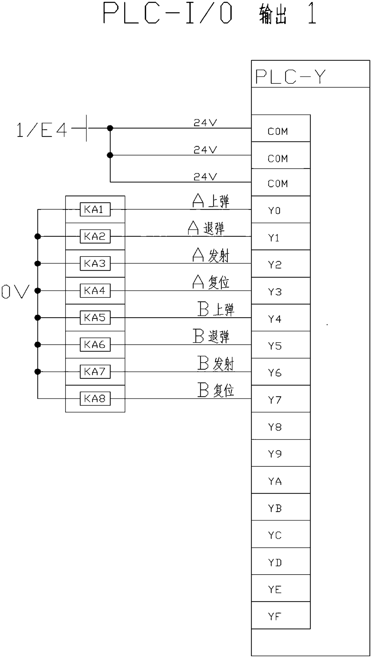
[0029] A special projectile robot automatic control system for metallurgy, its composition comprises: contactor switch, described contactor switch comprises contactor switch KA1, contactor switch KA2, contactor switch KA3, contactor switch KA4, contactor switch KA5 , contactor switch KA6, contactor switch KA7, contactor switch KA8, the contactor switch KA1 controls A to bounce, the contactor switch KA2 controls A to unbounce, and the contactor switch KA3 controls A to launch , the contactor switch KA4 controls A to reset, the contactor switch KA5 controls B to bounce, the contactor switch KA6 controls B to unbounce, the contactor switch KA7 controls B to launch, and the contactor switch KA7 controls B to launch. The contactor switch KA8 controls B to reset, the A springs up and connects to the crystal oscillator Y0, the A bounces back and connects to the crystal oscillator Y1, the A launch connects to the crystal oscillator Y2, the A reset connects to the crystal oscillator Y3,...

Embodiment 2

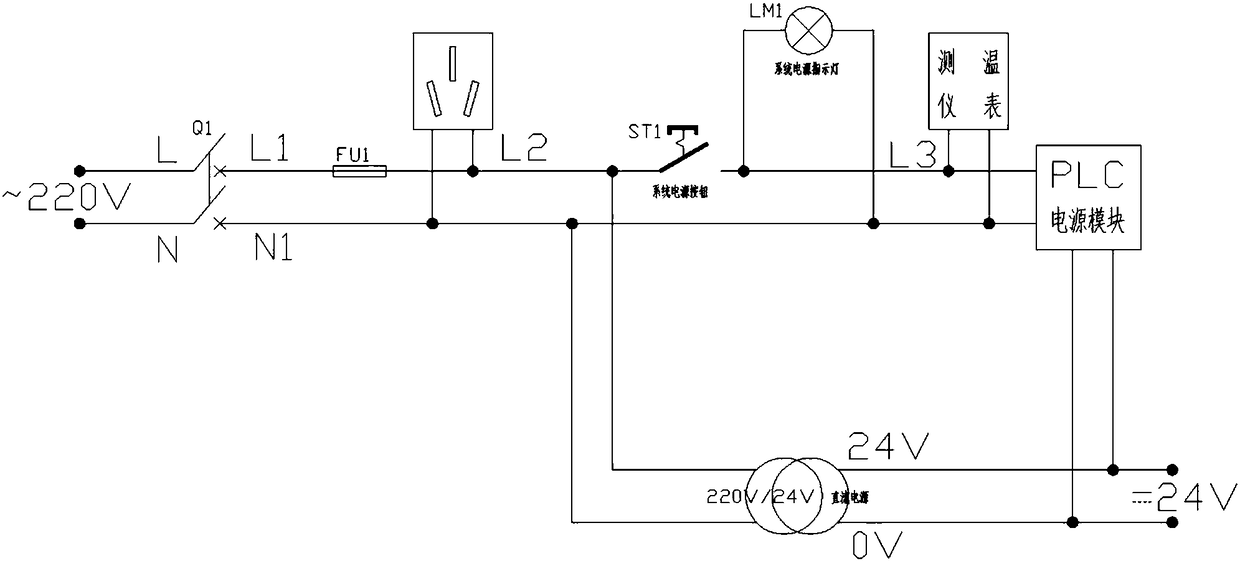
[0031] In the metallurgical projectile robot automatic control system described in Embodiment 1, the power module PLC-Y is connected to a DC power supply of 220V / 24V, the power module PLC-Y is connected to a temperature measuring instrument L3, and the temperature measuring instrument L3 is connected to the system power indicator LM1, the system power indicator LM1 is connected to the system power button ST1, the system power button ST1 is connected to the inductor L2, the inductor L2 is connected to the fuse FU1, and the fuse FU1 is connected to The contactor Q1 is connected to the 220V power supply.

Embodiment 3

[0033] In the metallurgical special-purpose projectile robot automatic control system described in Embodiment 1, the crystal oscillator Y series also includes crystal oscillator Y8, crystal oscillator Y9, crystal oscillator YA, crystal oscillator YB, crystal oscillator YC, crystal oscillator YD, crystal oscillator YE, and crystal oscillator YF.


PUM


Abstract

The invention provides a special metallurgical projectile robot automatic control system and control method. The system includes contactor switches, and the contactor switches include a contactor switch KA1, a contactor switch KA2, a contactor switch KA3, a contactor switch KA4, a contactor switch KA5, a contactor switch KA6, a contactor switch KA7 and a contactor switch KA8; the contactor switchKA1 controls A bullet loading in connection with a crystal oscillator Y0, the contactor switch KA2 controls A bullet unloading in connection with a crystal oscillator Y1, the contactor switch KA3 controls A emission in connection with a crystal oscillator Y2, the contactor switch KA4 controls A reset in connection with a crystal oscillator Y3, the contactor switch KA5 controls B bullet unloading in connection with a crystal oscillator Y4, the contactor switch KA6 controls B bullet unloading in connection with a crystal oscillator Y5, the contactor switch KA7 controls B emission in connection with a crystal oscillator Y6, and the contactor switch KA8 controls B reset in connection with a crystal oscillator Y7. The system is applied to special steel enterprises, stainless steel enterprises,machinery manufacturing and military enterprises.

Description

Technical field: [0001] The invention relates to an automatic control system and a control method of a metallurgical projectile robot. Background technique: [0002] Because the projectile needs to be injected into the molten steel at high speed in a very short time, the control system requires fast launch speed, accurate control, and high force. The control without the projectile method cannot meet the requirements, and the effect cannot meet the demand. Invention content: [0003] The object of the present invention is to provide a kind of automatic control system and control method of metallurgical special-purpose projectile robot that the stability, effectiveness and realizability of the whole system are all controlled by PLC functions. [0004] Above-mentioned purpose realizes by following technical scheme: [0005] A special projectile robot automatic control system for metallurgy, its composition comprises: contactor switch, described contactor switch comprises con...

Claims


Application Information

Patent Timeline
Patent Type & Authority Applications(China)
IPC IPC(8): G05B19/05
CPCG05B19/054G05B2219/1103
Inventor 李星野王军刘伯驰张卫东冯海波
Owner 黑龙江省冶金研究所
Learn More