
MIPI C-Phy TX output state conversion control circuit

A technology for switching control and output states, applied in the field of mobile communication, can solve the problems of high hardware overhead, complex combinational logic, and high cost, and achieve the effect of small circuit scale, simple combinational logic, and increased bandwidth.

Active Publication Date: 2018-07-27
LONTIUM SEMICON CORP
View PDF7 Cites 0 Cited by
  • Summary
  • Abstract
  • Description
  • Claims
  • Application Information

AI Technical Summary

Problems solved by technology

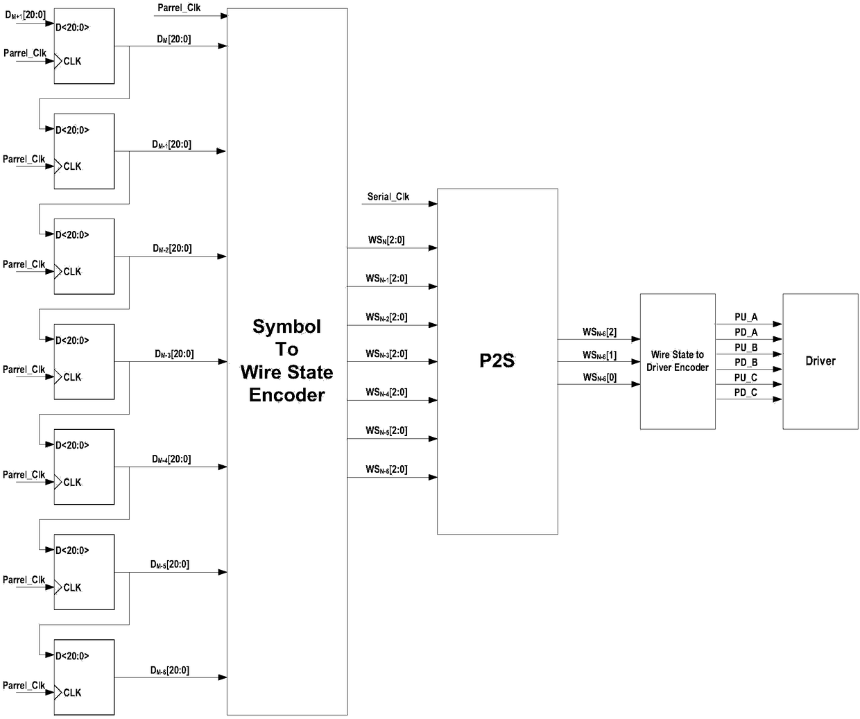
The idea of ​​this scheme is the simplest, but the hardware overhead is high. For example, the symbols of the two clock cycles before and after have a total of 6 bits, and the permutations and combinations have a total of 2 bits. 6 = 64 arrangements, considering the actual C-PHY protocol, each symbol has 5 possible values, so there are 5 × 5 = 25 combinations, so the combination logic of the encoding circuit requires 25 input ports, corresponding to 25 input data combination, the circuit scale is relatively large
Moreover, the more complex the combinational logic, the more it will affect the fastest frequency of the entire circuit, thereby reducing the bandwidth of the entire transmission interface
Both scheme 1 and scheme 2 are theoretically feasible. According to these two ideas, the circuit function can be finally realized, but the cost will be too high

Method used


Image

  • MIPI C-Phy TX output state conversion control circuit
  • MIPI C-Phy TX output state conversion control circuit
  • MIPI C-Phy TX output state conversion control circuit

Examples


Embodiment

[0051] figure 2 A circuit diagram of a MIPI C-Phy TX terminal output state conversion control circuit provided by the embodiment of the present application.

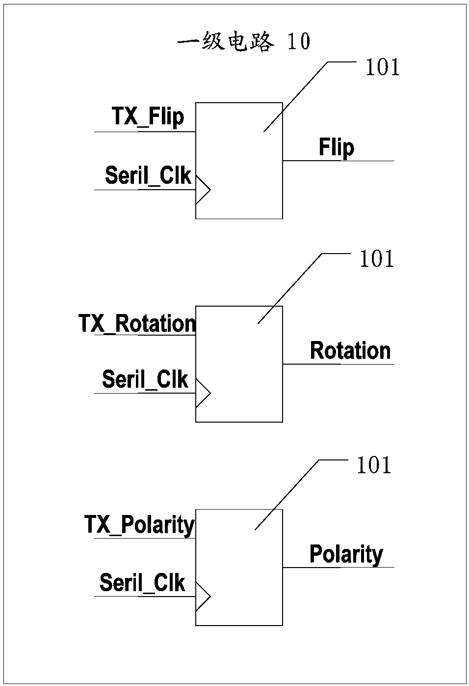
[0052] Such as figure 2 As shown, the conversion control circuit provided by this embodiment is applied in MIPI, and specifically includes a primary circuit 10 , a secondary circuit 20 , a tertiary circuit 30 and a drive control circuit 40 .

[0053] The primary circuit 10 is connected with the parallel-serial conversion circuit of MIPI, and is used to receive the character signal output by the parallel-serial conversion circuit, and output Flip signal, Rotation signal and Polarity signal according to the character signal and the working clock signal of the system. Flip signal refers to the state jump signal, only flipping polarity; Rtation signal refers to the state jump mode signal on the transmission line, with two directions of CW\CCW, CW stands for clockwise direction, CCW stands for counterclockwise direction; P...


PUM


Abstract

The invention provides an MIPI C-Phy TX output state conversion control circuit. The conversion control circuit comprises a first-stage circuit, a second-stage circuit, a third-stage circuit and a driver control circuit. The first-stage circuit is used for outputting a Flip signal, a Rotation signal and a Polarity signal according to a character signal and a work clock signal output by a parallel-serial conversion circuit of an MIPI; the second-stage circuit is a ring circuit; the ring circuit is used for outputting an A signal, a B signal and a C signal according to the Flip signal, the Rotation signal, the Polarity signal, the work clock signal and a reset control signal; the third-stage circuit is used for outputting a first output signal, a second output signal and a third output signal according to the A signal, the B signal, the C signal, the work clock signal and the reset control signal as an initial value; and the driver control circuit is used for performing coding processingon the first output signal, the second output signal and the third output signal to obtain conversion control signals. The circuit ensures that the character signal output by the parallel-serial conversion circuit can be effectively converted into a state on a transmission line and output to an RX end.

Description

technical field [0001] The present application relates to the technical field of mobile communication, and more specifically, relates to a conversion control circuit of the output state of the MIPI C-Phy TX terminal. Background technique [0002] MIPI (mobile industry processor interface) is a mobile industry processor interface, an open standard and specification initiated by the MIPI Alliance for processors used in mobile devices. C-Phy is the latest interface protocol of MIPI. Unlike the D-Phy and M-Phy before MIPI, which uses a differential signal transmission method consisting of two lines, C-Phy uses three lines to transmit signals, and the voltages on the three lines are different. , get different online status Wire State. The TX end will map the conversion layer 21bit data according to the 16bit real data that needs to be transmitted through the lookup table, and 21bit contains 7 characters symbol. If it is necessary to transmit the 7 symbols to the RX terminal, th...

Claims


Application Information

Patent Timeline
IPC IPC(8): G06F13/40H03K19/00
CPCG06F13/4072H03K19/0002
Inventor 季翔宇陈余陶成
Owner LONTIUM SEMICON CORP
Learn More