
Outdoor multifunctional novel power distribution cabinet

A multi-functional, power distribution cabinet technology, applied in substation/distribution device housing, electrical components, substation/switch layout details, etc., can solve problems affecting equipment service life, poor heat dissipation performance, affecting equipment power supply, etc. The effect of protecting safety, ensuring dryness and preventing theft

Inactive Publication Date: 2018-07-27
合肥龙智机电科技有限公司
View PDF4 Cites 4 Cited by
  • Summary
  • Abstract
  • Description
  • Claims
  • Application Information

AI Technical Summary

Problems solved by technology

[0003] As a common power equipment, the power distribution cabinet is often used in various electrical equipment. Now some unattended power distribution cabinets are often installed outdoors, but the equipment inside the power distribution cabinet is generally more precious, so it is often unscrupulous. Molecular theft, and in some low-lying places, the power distribution cabinet is often affected when it rains heavily, thus affecting the power supply of the equipment, and the structure of the current power distribution cabinet is simple, so the heat dissipation performance of the equipment is poor, and the internal cannot Keep it dry, which will affect the service life of the equipment

Method used

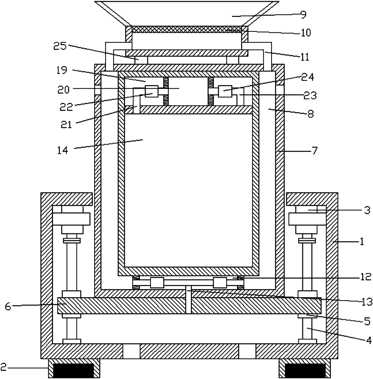
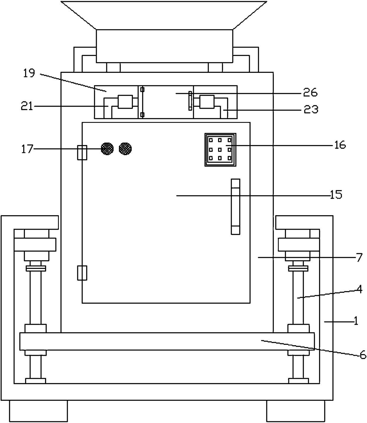

Image

  • Outdoor multifunctional novel power distribution cabinet
  • Outdoor multifunctional novel power distribution cabinet
  • Outdoor multifunctional novel power distribution cabinet

Examples


Embodiment Construction

[0018] It should be noted that, in the case of no conflict, the embodiments of the present invention and the features in the embodiments can be combined with each other.

[0019] In describing the present invention, it should be understood that the terms "center", "longitudinal", "transverse", "upper", "lower", "front", "rear", "left", "right", " The orientations or positional relationships indicated by "vertical", "horizontal", "top", "bottom", "inner" and "outer" are based on the orientations or positional relationships shown in the drawings, and are only for the convenience of describing the present invention and Simplified descriptions, rather than indicating or implying that the device or element referred to must have a particular orientation, be constructed and operate in a particular orientation, and thus should not be construed as limiting the invention. In addition, the terms "first", "second", etc. are used for descriptive purposes only, and should not be understood ...


PUM


Abstract

The invention discloses an outdoor multifunctional novel power distribution cabinet. The outdoor multifunctional novel power distribution cabinet comprises a connecting frame; a motor is arranged at the upper end of the interior of the connecting frame; a lead screw is arranged on the lower side of the motor; an inner thread bushing is arranged on the lead screw; a supporting plate is arranged outside the inner thread bushing; an outer shell is arranged on the upper side of the supporting plate; hollow cavities are formed in the left and right ends in the shell; a water connecting cover is arranged on the upper side of the outer shell; connecting pipes are arranged on the left and right sides of the water connecting cover; an inner shell is arranged on the inner sides of the hollow cavities; a connecting cavity is formed in the lower end between the inner shell and the outer shell; a drain pipe is arranged in the connecting cavity; a cabinet door is arranged on the front sides of the inner shell and the outer shell; a digital coded lock is arranged at the right end of the front side of the cabinet door; an alarm is arranged on the upper side of the left end of the cabinet door; a concave opening is formed in the upper side of the inner shell; a drying cavity is formed in the concave opening; and an air exhausting pipe and a drain pipe are arranged on the left and right sides ofthe drying cavity. According to the outdoor multifunctional novel power distribution cabinet, ventilation, heat dissipation and dry state maintaining of the power distribution cabinet can be realizedeffectively, and stealing of the equipment and rainwater entrance can be prevented effectively, thereby ensuring safe use of the equipment.

Description

technical field [0001] The invention relates to electric equipment, in particular to a new outdoor multi-functional power distribution cabinet. Background technique [0002] Power equipment (power system) is a power production and consumption system composed of power generation, power transmission, power transformation, power distribution and power consumption. It converts the primary energy in nature into electricity through the power generation device, and then supplies the electricity to various users through power transmission, transformation and distribution. It mainly includes two categories of power generation equipment and power supply equipment. Power generation equipment is mainly power plant boilers, steam turbines, gas turbines, water turbines, generators, point motors, transformers, etc. Power supply equipment is mainly transmission lines and transformers of various voltage levels. , contactor, etc. [0003] As a common electrical equipment, the power distribu...

Claims


Application Information

Patent Timeline
Patent Type & Authority Applications(China)
IPC IPC(8): H02B1/30H02B1/56H02B1/28H02B1/32
CPCH02B1/30H02B1/28H02B1/303H02B1/306H02B1/32H02B1/565
Inventor 陈薇
Owner 合肥龙智机电科技有限公司
Learn More