
Communication control-based low-voltage reactive compensation device

A compensation device and technology on the low-voltage side, applied in reactive power compensation, reactive power adjustment/elimination/compensation, circuit devices, etc., can solve problems such as inconvenient maintenance, contactors affecting normal compensation, complicated wiring, etc., and achieve installation hours reduction, convenient on-site maintenance, and improved power factor

Inactive Publication Date: 2018-07-27
广州峰控电力科技有限公司
View PDF0 Cites 2 Cited by
  • Summary
  • Abstract
  • Description
  • Claims
  • Application Information

AI Technical Summary

Problems solved by technology

[0003] The traditional reactive power compensation device switches the three phases of the capacitor at the same time, does not have the function of phase separation compensation, and cannot solve the reactive power compensation problem of the unbalanced three phases; the switching process uses the traditional AC contactor, which cannot realize the voltage zero-crossing input , Current zero-crossing cutoff, AC contactor frequently cuts off load current, high failure rate
In addition, the wiring of the traditional reactive power compensation device is complex, and the entire reactive power compensation cabinet is covered with power lines and control lines, which makes maintenance inconvenient. If the compensation capacity is insufficient, it is difficult to expand the capacity
Once the controller fails, the entire compensation cabinet will be paralyzed, and the failure of the contactor will affect its normal compensation; and the compensation capacity of the same capacity, the traditionally required cabinet is larger

Method used


Image

  • Communication control-based low-voltage reactive compensation device
  • Communication control-based low-voltage reactive compensation device
  • Communication control-based low-voltage reactive compensation device

Examples


Embodiment Construction

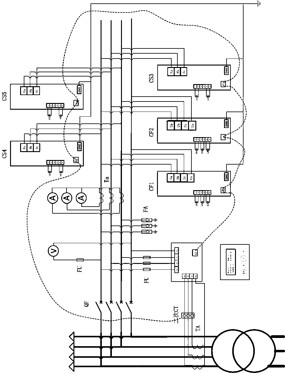
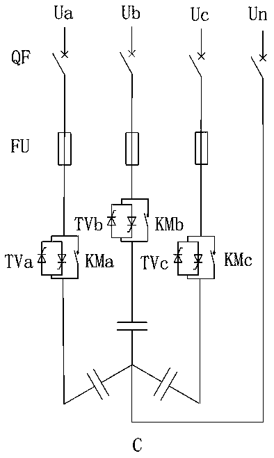
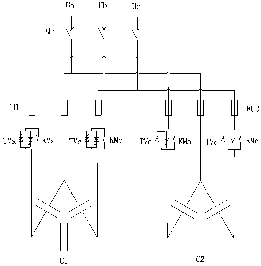
[0027] The technical solution of the present invention will be further described below in conjunction with the accompanying drawings and embodiments. The present invention provides a reactive power compensation device based on communication control, see figure 1 , The reactive power compensation device mainly includes: main switch QF, voltmeter V loop, ammeter A loop, lightning arrester FA loop, controller JKW loop, split-phase intelligent capacitor CF loop, common-phase intelligent capacitor CS loop, and secondary CT.

[0028] The V circuit of the voltmeter is connected to the A and N phases of the transformer through the fuse FU and displays the voltage of the A phase at the low voltage side of the transformer.

[0029] The A circuit of the ammeter is connected in series on the secondary side of the current transformer Ta. The current transformer Ta is a feed-through type. The transformation ratio is determined according to the capacity of reactive power compensation. A, B, ...


PUM


Abstract

The invention relates to a communication control-based low-voltage reactive compensation device. Communication connection is performed between a reactive compensation controller and an intelligent capacitor and between intelligent capacitors, no other control loop is needed; zero-voltage putting and zero-voltage removal of the capacitor are achieved by arranging a composite switch in each intelligent capacitor, and the composite switch comprises an AC relay and a silicon-controlled rectifier; the reactive compensation controller is provided with an AC acquisition module, a communication moduleand a special chip, active powers, reactive powers and power factors of phases A, B and C of a low-voltage side of a transformer are calculated according to a current signal of a secondary side of acurrent transformer and a directly-acquired voltage signal, switching and removal of the intelligent capacitor are controlled by a communication mode according to a calculation result, a power factorof a user is stabilized within a set range in real time, the output power of the transformer is improved, the electric energy quality is improved, and the line loss is reduced. The reactive compensation device provided by the invention employs modular design and is simple in structure, and capacity expansion is facilitated.

Description

technical field [0001] The invention relates to a low-voltage reactive power compensation device based on communication control, which is especially suitable for places with large load changes, unbalanced three-phases, and frequent switching of capacitors. Background technique [0002] At present, when my country's residential and commercial transformers are installed, the power supply department requires users to configure corresponding reactive power compensation equipment. For cost considerations, the user generally adopts the traditional reactive power compensation control, that is, one output corresponds to one switching switch, and the capacitor is switched through point-to-point control to improve the power factor of the system. [0003] The traditional reactive power compensation device switches the three phases of the capacitor at the same time, does not have the function of phase separation compensation, and cannot solve the reactive power compensation problem of t...

Claims


Application Information

Patent Timeline
IPC IPC(8): H02J3/18H02J3/26
CPCY02E40/30Y02E40/50H02J3/1821H02J3/26
Inventor 陈小奋陈谨
Owner 广州峰控电力科技有限公司
Learn More