Rotor structure, permanent magnet auxiliary synchronous reluctance motor and electric vehicle

A technology of rotor structure and permanent magnet, which is applied to electric vehicles, synchronous motors with stationary armatures and rotating magnets, synchronous machines, etc., can solve the problems of low motor efficiency, achieve improved anti-demagnetization ability, increase inductance, and improve Effect of Motor Efficiency

Active Publication Date: 2018-07-27
ZHUHAI GREE REFRIGERATION TECH CENT OF ENERGY SAVING & ENVIRONMENTAL PROTECTION
View PDF5 Cites 8 Cited by
  • Summary
  • Abstract
  • Description
  • Claims
  • Application Information

AI Technical Summary

Problems solved by technology

[0003] The main purpose of the present invention is to provide a rotor structure, permanent magnet assisted synchronous reluctance motor and electric vehicle, to solve the problem of low motor efficiency in the prior art

Method used


Image

  • Rotor structure, permanent magnet auxiliary synchronous reluctance motor and electric vehicle
  • Rotor structure, permanent magnet auxiliary synchronous reluctance motor and electric vehicle
  • Rotor structure, permanent magnet auxiliary synchronous reluctance motor and electric vehicle

Examples


Embodiment Construction

[0057] It should be noted that the embodiments in this application and the features in the embodiments can be combined with each other if there is no conflict. Hereinafter, the present invention will be described in detail with reference to the drawings and in conjunction with the embodiments.

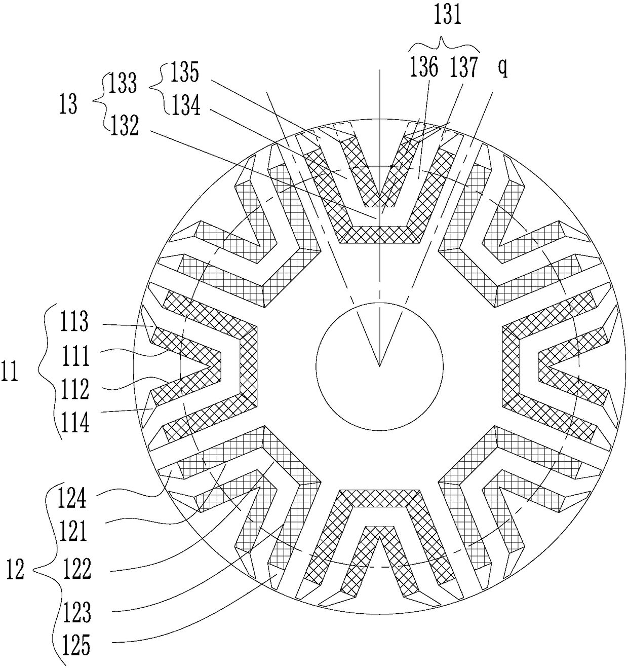
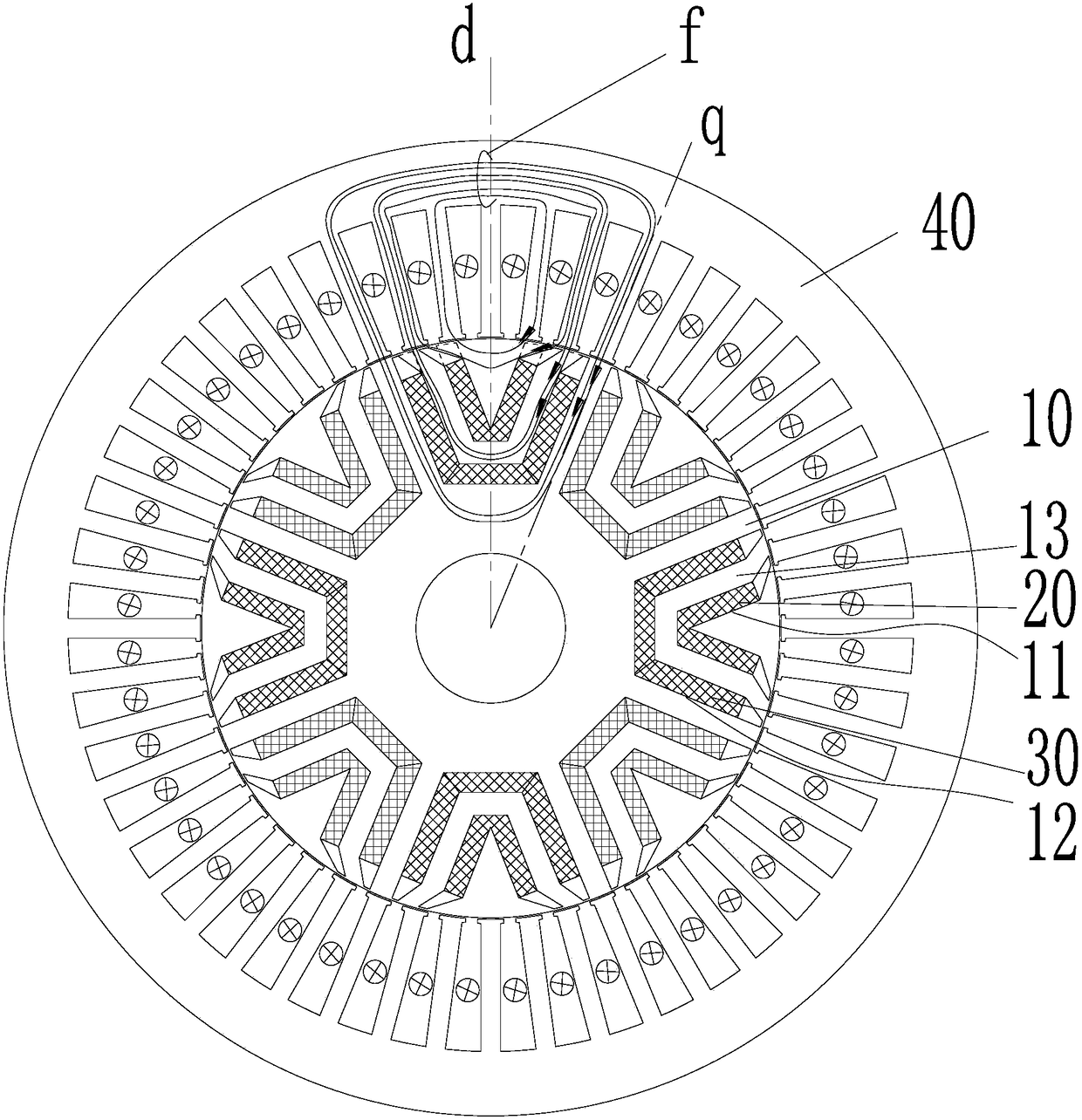
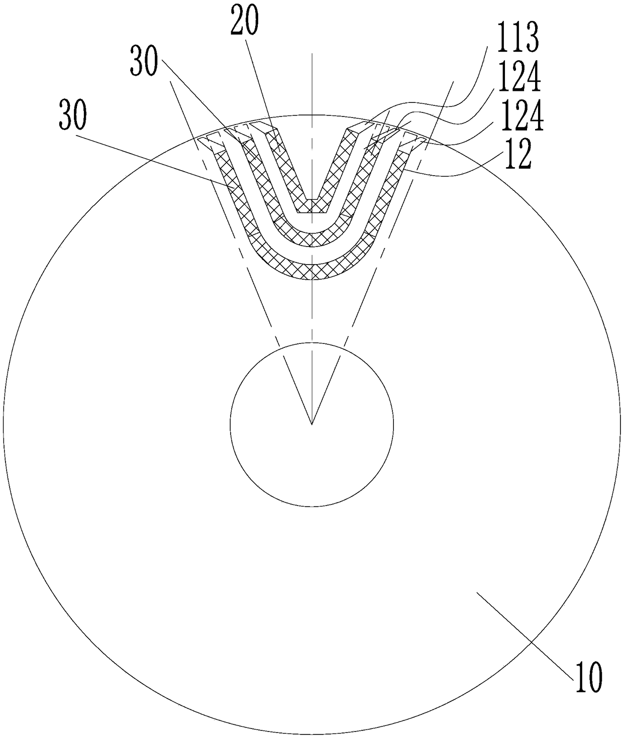
[0058] Combine Figure 1 to Figure 8 , Figure 10 to Figure 19 As shown, according to an embodiment of the present invention, a rotor structure is provided.

[0059] Specifically, the rotor structure includes a rotor body 10, and a permanent magnet slot group is provided on the rotor body 10, the permanent magnet slot group includes a multilayer permanent magnet slot, the multilayer permanent magnet slot includes a first permanent magnet slot 11, and a first permanent magnet The slot 11 includes a first permanent magnet slot section 111 and a first folding slot 113. The first end of the first permanent magnet slot section 111 extends toward the shaft hole of the rotor body 10, and the secon...


PUM


Abstract

The invention provides a rotor structure, a permanent magnet auxiliary synchronous reluctance motor and an electric vehicle. The rotor structure includes a rotor body. A permanent magnet slot group isdisposed on the rotor body. The permanent magnet slot group includes a plurality of permanent magnet slots. The multilayer permanent magnet slot includes a first permanent magnet slot. The first permanent magnet slot includes a first permanent magnet slot segment and a first hinge slot. The first end of the first chamfer is in communication with the second end of the first permanent magnet slot segment. A second end of the first chamfer extends toward an outer edge of the rotor body. A distance from a midpoint of the second end of the first chamfer adjacent the outer edge of the rotor body toa point at which the geometric centerline of the first permanent magnet slot intersects the outer edge of the rotor body is A. The width of the end of the second end of the first permanent magnet slot segment is M, where 0.6 M <=A. This arrangement optimizes the magnetic circuit of the rotor structure, so that the overall anti-demagnetization capability of the rotor structure is effectively improved, and the motor efficiency of the rotor structure with the structure is improved.

Description

Technical field [0001] The present invention relates to the technical field of electrical equipment, in particular to a rotor structure, a permanent magnet auxiliary synchronous reluctance motor and an electric vehicle. Background technique [0002] Electric vehicles have the characteristics of energy saving and environmental protection, and have been developed rapidly. In order to realize the functions of high power density and high efficiency of the existing electric vehicle drive motors, more and more motors use high-performance rare earth permanent magnet motors. Rare earth permanent magnet motors can achieve high efficiency and high power density, mainly relying on high performance rare earth permanent magnets. Currently, neodymium iron boron rare earth permanent magnets are the most widely used. However, rare earth is a non-renewable resource, and the price is relatively high, and the price of rare earth fluctuates greatly, resulting in high production cost of electric veh...

Claims


Application Information

Patent Timeline
Patent Type & Authority Applications(China)
IPC IPC(8): H02K1/27H02K29/03
CPCH02K29/03H02K2213/03H02K1/274H02K1/2766H02K21/12H02K19/103Y02T10/64
Inventor 黄辉胡余生陈彬肖勇童童卢素华
Owner ZHUHAI GREE REFRIGERATION TECH CENT OF ENERGY SAVING & ENVIRONMENTAL PROTECTION
Why Eureka
Try Eureka