Reversing device of pumping unit

A technology of reversing device and pumping unit, which is applied in the direction of production fluid, wellbore/well parts, earthwork drilling and production, etc., which can solve the problems of heavy load and high energy consumption, and achieve the purpose of improving service life, saving energy and reducing energy consumption Effect

Inactive Publication Date: 2018-07-31
赵顺全
View PDF0 Cites 0 Cited by
  • Summary
  • Abstract
  • Description
  • Claims
  • Application Information

AI Technical Summary

Problems solved by technology

[0004] The technical problem mainly solved by the invention: Aiming at the problems of large load and high energy consumption of the existing reversing device, the present invention proposes a reversing device for pumping units

Method used


Image

  • Reversing device of pumping unit

Examples


Embodiment Construction

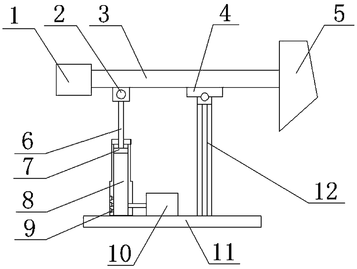
[0014] A reversing device for a pumping unit, comprising a base 11, a beam 3 and a piston mechanism 8, the left side of the beam 3 is provided with a counterweight box 1, the right side of the beam 3 is a donkey head 5, and the beam 3 is connected to the bracket through the hinge mechanism 4 12, the bracket 12 is set on the base 11, the piston mechanism 8 is set on the base 11, the right side of the piston mechanism 8 is connected to the air pump 10, the piston mechanism 8 is provided with a piston 7, and the piston 7 is connected to the connecting rod 6 , the connecting rod 6 is connected with the beam 3 through the hinge mechanism 2, and the piston mechanism 8 is provided with an electromagnetic valve 9. An application method of the reversing device of a pumping unit is as follows: when the pumping device is started, the air pump 10 rushes high-pressure gas into the piston mechanism 8, the electromagnetic valve 9 is closed, and the piston 7 moves upward under the action of th...


PUM


Abstract

The invention relates to a reversing device of a pumping unit and belongs to the technical field of petroleum mechanical equipment. The reversing device comprises a base, a crossbeam and a piston mechanism; a counterweight box is arranged on the left side of the crossbeam, and a horse head is arranged on the right side of the crossbeam; the crossbeam is connected with a bracket through a hinge mechanism; the bracket is arranged on the base; the piston mechanism is arranged on the base, and the right side of the piston mechanism is connected with an air pump; a piston is arranged in the pistonmechanism and connected with a connecting rod; the connecting rod is connected with the crossbeam through a hinge mechanism; and electromagnetic valves are arranged at the bottom of the piston mechanism. Through the piston mechanism and a counterweight device, energy required for driving the crossbeam to downwards move is effectively saved, energy consumption of the reversing device is greatly reduced, the load borne by the connecting rod is reduced, and the service life of the reversing device is prolonged.

Description

technical field [0001] The invention relates to a reversing device for an oil pumping unit, which belongs to the technical field of petroleum machinery equipment. Background technique [0002] With the continuous development of oil fields, heavy oil reserves account for as much as 50% of my country's crude oil reserves, and more and more oil fields have entered the stage of high water content exploitation. In this case, the pressure at the bottom of the oil well decreases, and the self-spraying ability is gradually lost, basically turning from the self-spraying stage to the mechanical production stage. Since the height of the oil level and the filling rate are variable, it is required that the stroke of the sucker rod pump can be adjusted with the height of the oil level. change with change. And along with the carrying out of exploitation, the depth of oil well also constantly increases, causes the suspension point load of pumping unit to also constantly increase. In this...

Claims


Application Information

Patent Timeline
IPC IPC(8): E21B43/00
CPCE21B43/127
Inventor 赵顺全赵兴华朱华
Owner 赵顺全
Why Eureka
Try Eureka