Multi-stage hydraulic machine continuously variable transmission for heavy vehicle

A continuously variable transmission, hydraulic machinery technology, applied in mechanical equipment, transmission parts, fluid transmission, etc., can solve the problems of increasing the complexity of the transmission mechanical structure, unable to achieve continuous transmission, and increasing costs, and achieve flexible shifting. Convenience, improved shifting range, and improved dynamic performance

Inactive Publication Date: 2018-07-31
HENAN UNIV OF SCI & TECH
View PDF5 Cites 1 Cited by
  • Summary
  • Abstract
  • Description
  • Claims
  • Application Information

AI Technical Summary

Problems solved by technology

Although the stepped transmission in the prior art can meet certain requirements by shifting gears, it can only transmit power according to a fixed transmission ratio, and cannot realize continuous speed change. If the gears are increased, the complexity of the mechanical structure of the transmission will be increased. Moreover, the cost increases and the operation is difficult, which seriously restricts the improvement of its performance.

Method used


Image

  • Multi-stage hydraulic machine continuously variable transmission for heavy vehicle
  • Multi-stage hydraulic machine continuously variable transmission for heavy vehicle
  • Multi-stage hydraulic machine continuously variable transmission for heavy vehicle

Examples


Embodiment 1

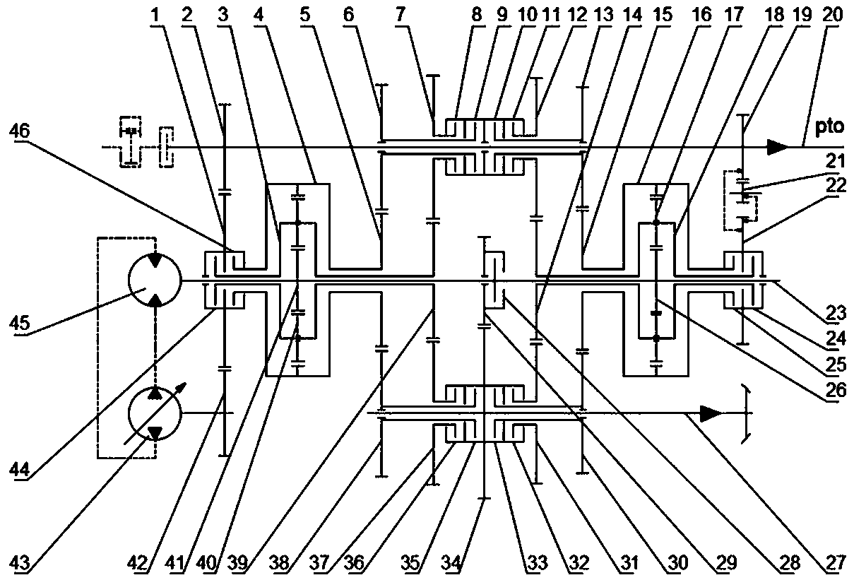
[0036] Embodiment 1, a kind of purely mechanical transmission form M2 gear of multi-stage hydraulic mechanical continuously variable transmission for heavy vehicles: as figure 2 As shown, the power transmitted from the engine realizes torque splitting at the first gear 2, and all the way is transmitted to the working device through the power shaft 20; all the way is transmitted to the third clutch housing through the second gear 1, and the front ring gear clutch 46 is engaged , the power is transmitted to the second clutch housing through the fifth gear 5 and the sixth gear 38 , the sixth gear clutch 35 is engaged, and finally the power is transmitted to the main output shaft 27 .

[0037] Similar to the M2 gear of the purely mechanical transmission form of the front planetary row, there is also the M1 gear; similarly, the purely mechanical transmission form of the rear planetary row has M3 gear and M4 gear, which will not be described in detail here. The present invention ha...

Embodiment 2

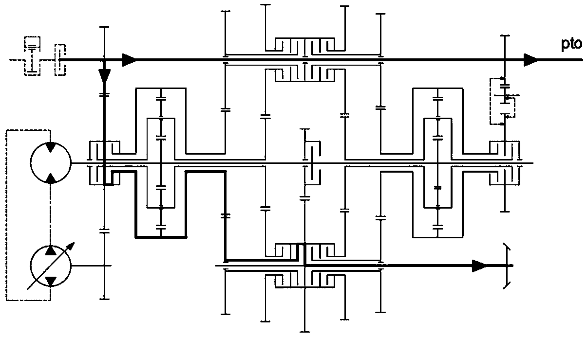
[0038] Embodiment 2. A multi-stage hydraulic-mechanical continuously variable transmission for heavy-duty vehicles is converging in the front planetary row converging device without passing through the output of the first clutch housing in the form of hydraulic-mechanical hybrid transmission HM2 gear: as image 3 As shown, the power transmitted from the engine realizes torque splitting at the first gear 2, and all the way is transmitted to the working device through the power shaft 20; all the way is transmitted to the third clutch housing through the second gear 1, and the front ring gear clutch 46 is engaged , the torque is divided again in the third clutch housing, one way is transmitted to the hydraulic circuit and transmitted to the front sun gear 41, and the other is transmitted to the front ring gear 4, and the power is realized at the front planetary row. 3 is transmitted to the eighth gear 39, the ninth gear 37, the ninth gear clutch 36 is engaged, and finally the powe...

Embodiment 3

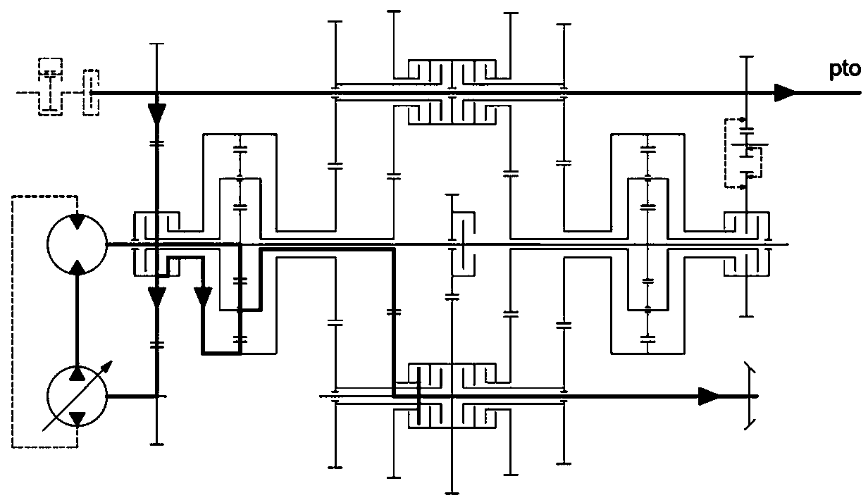
[0040] Embodiment 3. A multi-stage hydraulic-mechanical continuously variable transmission for heavy-duty vehicles in which the front planetary row confluences and passes through the first clutch housing to output the hydraulic-mechanical hybrid transmission form HM8 gear: as Figure 4 As shown, the power transmitted from the engine realizes torque splitting at the first gear 2, and all the way is transmitted to the working device through the power shaft 20; all the way is transmitted to the third clutch housing through the second gear 1, and the front ring gear clutch 46 is engaged , the torque is divided again in the third clutch housing, one way is transmitted to the front sun gear 41 through the hydraulic circuit, and the other is transmitted to the front ring gear 4, and the power is realized at the front planetary row. Transmission to the eighth gear 39, the seventh gear 7, the seventh gear clutch 8 and the twelfth gear clutch 11 are engaged, the power is transmitted to t...


PUM


Abstract

The invention relates to the field of vehicle transmission equipment, in particular to a multi-stage hydraulic machine continuously variable transmission for a heavy vehicle. The multi-stage hydraulicmachine continuously variable transmission for the heavy vehicle comprises a mechanical transmission assembly, a hydraulic transmission assembly, a power shaft, a motor shaft and a main output shaft,wherein the power shaft, the motor shaft and the main output shaft are parallel; the mechanical transmission assembly comprises a front planetary row confluence device, a rear planetary row confluence device, a fixed shaft gear pair and a plurality of clutch execution devices used for band switch; the hydraulic transmission assembly comprises a variable-displacement hydraulic pump and a quantitative hydraulic motor which are arranged in series; an input shaft of the variable-displacement hydraulic pump is fixedly connected with a third gear; and an output shaft of the quantitative hydraulic motor is fixedly connected with the end, close to the front planetary row confluence device, of the motor shaft. The multi-stage hydraulic machine continuously variable transmission for the heavy vehicle not only can achieve multi-stage large-range continuously variable speed adjusting performance, but also can meet the multi-mode requirements for driving of the vehicle under different working conditions.

Description

technical field [0001] The invention relates to the field of vehicle transmission equipment, in particular to a multi-stage hydraulic mechanical continuously variable transmission for heavy vehicles. Background technique [0002] The operating conditions of high-power heavy-duty vehicles are complex, and the external load fluctuates frequently. The transmission is required to change the speed and torque in a timely manner to adapt to the continuous changes of the actual load, so as to ensure the power and fuel economy of the vehicle. Although the stepped transmission in the prior art can meet certain requirements through gear shifting, it can only transmit power according to a fixed transmission ratio, and cannot realize continuous speed change. If the gears are increased, the complexity of the mechanical structure of the transmission will be increased. Moreover, the cost increases and the operation is difficult, which seriously restricts the improvement of its performance. ...

Claims


Application Information

Patent Timeline
Patent Type & Authority Applications(China)
IPC IPC(8): F16H47/04F16H57/023
CPCF16H47/04F16H57/023
Inventor 曹付义李豪迪邓瑞涛张风丽马可王浩然崔梦凯李金龙
Owner HENAN UNIV OF SCI & TECH
Why Eureka
Try Eureka