Commercial exhaust kitchen

A kitchen and commercial technology, applied in the field of exhaust kitchens, can solve the problems of poor exhaust, damage to the appearance of building facades, pollution, etc., to achieve the effects of easy installation and fixing, economical cost savings, and increased air replenishment effect

Active Publication Date: 2018-07-31
吴联凯
View PDF11 Cites 0 Cited by
  • Summary
  • Abstract
  • Description
  • Claims
  • Application Information

AI Technical Summary

Problems solved by technology

However, there are several disadvantages: firstly, there are various exhaust pipes and windproof caps connected by users themselves, which damage the appearance of the building's facade; secondly, the oily fume discharged from the kitchen on the lower floor will enter the indoors of the residents on the upper floor, causing pollution; thirdly, When encountering high-speed head-on wind, there will be poor exhaust or backflow
[0009] First, although the oily fume on the upper part of the exhaust kitchen is relatively small, the position of the fifth communicating pipe 20 and the exhaust fan 4 are basically at a horizontal line, and the effect of the fifth communicating pipe 20 can directly increase the gas supply effect of the kitchen. However, since the air is directly circulated, it will still cause the oily fume escaping to the top of the kitchen during the cooking process to pollute the outside atmosphere. Although closing the connecting pipe can solve this problem, it will greatly reduce the ventilation and exhaust effect of the kitchen. Therefore, how to ensure the efficient ventilation and exhaust effect of the kitchen while still ensuring the purification of oil fume is a contradiction that needs to be solved;
[0010] Second, the first-stage purification equipment 10 is equipped with a porous filter ceramic body; the preparation of the porous filter ceramic includes powder preparation, compression molding, and high-temperature sintering, and the porous filter ceramic body is directly placed on the first-level filter during installation. In the purification equipment 10, the two ends are fixed in a simple way such as a simple bayonet or a screw-fixed filter screen (such as non-woven fabric). damage, resulting in unnecessary economic losses for users

Method used


Image

  • Commercial exhaust kitchen
  • Commercial exhaust kitchen
  • Commercial exhaust kitchen

Examples


Embodiment 1

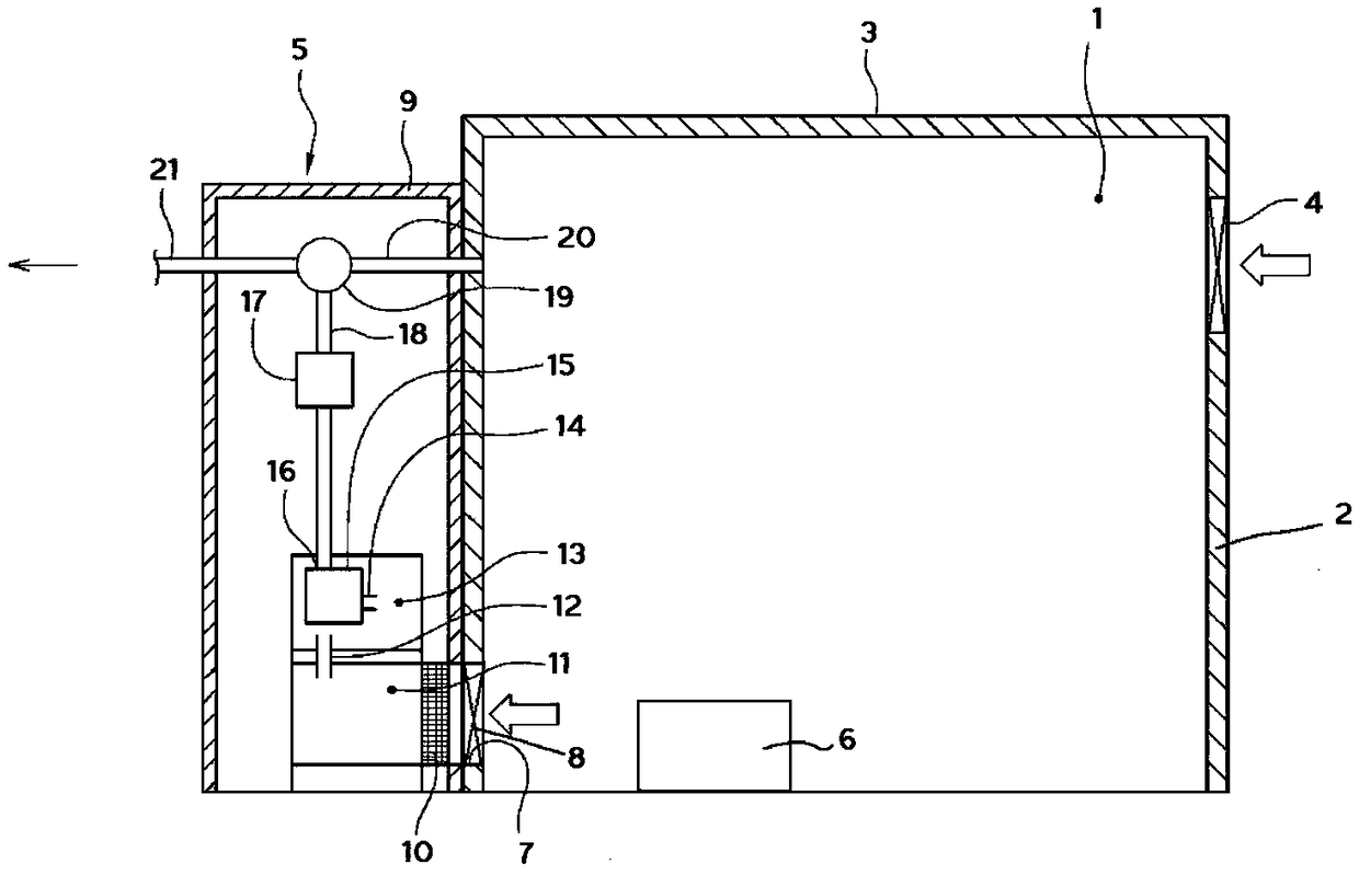
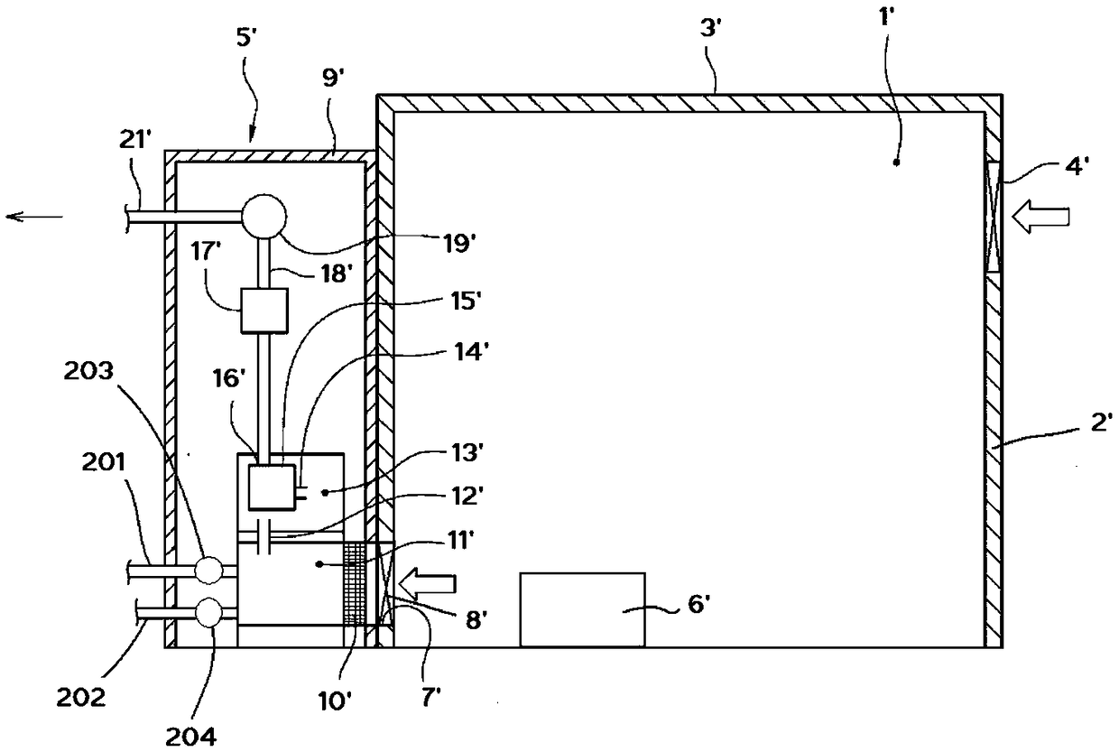
[0034] Such as Figure 2-3 As shown, a commercial exhaust kitchen 1' includes a kitchen side wall 2', a kitchen ceiling 3', an exhaust fan 4', an external exhaust device 5', and a gas stove large pot stove 6', wherein the Exhaust device 5' is arranged on the outside of the kitchen side wall, and the gas stove cauldron stove is arranged inside the kitchen; a range hood is arranged above the gas stove cauldron stove (not shown in the figure, but It will be clear to those skilled in the art), and an exhaust air duct 7' is provided near the kitchen side wall of the external exhaust device, and an exhaust fan 8' is arranged on the exhaust air duct 7', and the range hood exhaust fume The pipeline is connected with the exhaust passage 7' (not shown in the figure, but those skilled in the art can understand); The first oil fume collecting chamber 11', the first connecting pipe 12', the second oil fume collecting chamber 13', the second connecting pipe 14', the secondary filtering equ...


PUM


Abstract

The invention discloses a commercial exhaust kitchen. The exhaust kitchen comprises kitchen side walls, a kitchen ceiling, an exhaust fan, an external exhaust device, a gas stove large pot hearth, a gas stove lampblack purifying device and first-grade purifying equipment, wherein a pretightening force adjusting device is arranged at a mounting end part of the first-grade purifying equipment. The commercial exhaust kitchen solves two difficulties of efficient kitchen exhausting and ventilation and lampblack purification, meanwhile, is convenient to install and fix a porous filter ceramic body in the purifying equipment, reduces atmospheric pollution, improves the kitchen air supply effect, and fully uses leftovers to greatly save the economical cost.

Description

technical field [0001] The invention relates to an exhaust kitchen suitable for a large gas cooker. Background technique [0002] The kitchen is a basic part of the house and the main place for people to cook. Due to the burning of various civil fuels, cooking fume and domestic garbage, the kitchen has become the "hardest hit area" of the residence, and the kitchen has also become one of the important sources of indoor air pollution in residential buildings. Kitchen exhaust gas is the main polluting gas in the kitchen. It includes two types: one is the exhaust gas released during the fuel combustion process, and the other is the substances produced by a series of physical and chemical changes of food and oil at high temperature. The two substances mix and spread rapidly in space, endangering people's physical and mental health. [0003] The most important components in cooking fumes are alkanes and alkenes, followed by organic acids, aldehydes and polycyclic aromatic hydro...

Claims


Application Information

Patent Timeline
Patent Type & Authority Applications(China)
IPC IPC(8): F24C15/20C04B38/00C04B35/14
CPCC04B35/14C04B38/00F24C15/20F24C15/2035
Inventor 吴联凯
Owner 吴联凯
Why Eureka
Try Eureka