Support mechanism

A technology of support mechanism and support structure, applied in camera, installation, optics and other directions, can solve the problems of difficulty in reducing the size and unfavorable product miniaturization.

Active Publication Date: 2018-07-31
TDK TAIWAN
View PDF7 Cites 2 Cited by
  • Summary
  • Abstract
  • Description
  • Claims
  • Application Information

AI Technical Summary

Problems solved by technology

However, if figure 1 As shown, in a general optical image stabilization device, the lens is arranged in the lens holder 100, and the lens holder 100 is movably arranged in the frame 200, wherein the frame 200 and the lower substrate 300 pass through the verti

Method used


Image

  • Support mechanism
  • Support mechanism
  • Support mechanism

Examples


Embodiment Construction

[0055] Embodiments of the present invention are described with reference to the accompanying drawings.

[0056] The foregoing and other technical contents, features and effects of the present invention will be clearly presented in the following detailed description of a preferred embodiment with reference to the accompanying drawings. The directional terms mentioned in the following embodiments, such as: up, down, left, right, front or rear, etc., are only referring to the directions of the attached drawings. Accordingly, the directional terms used are illustrative and not limiting of the present invention.

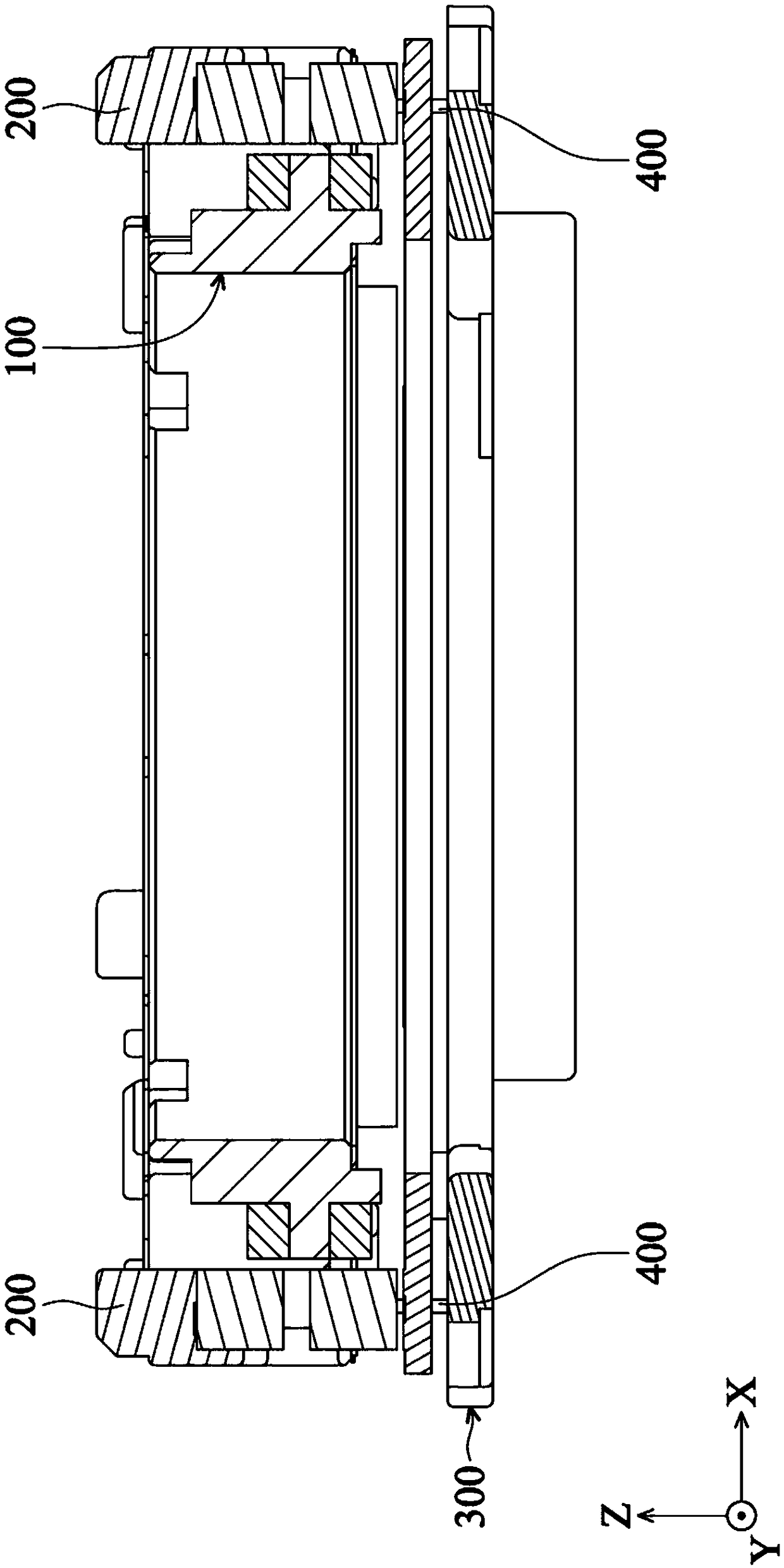
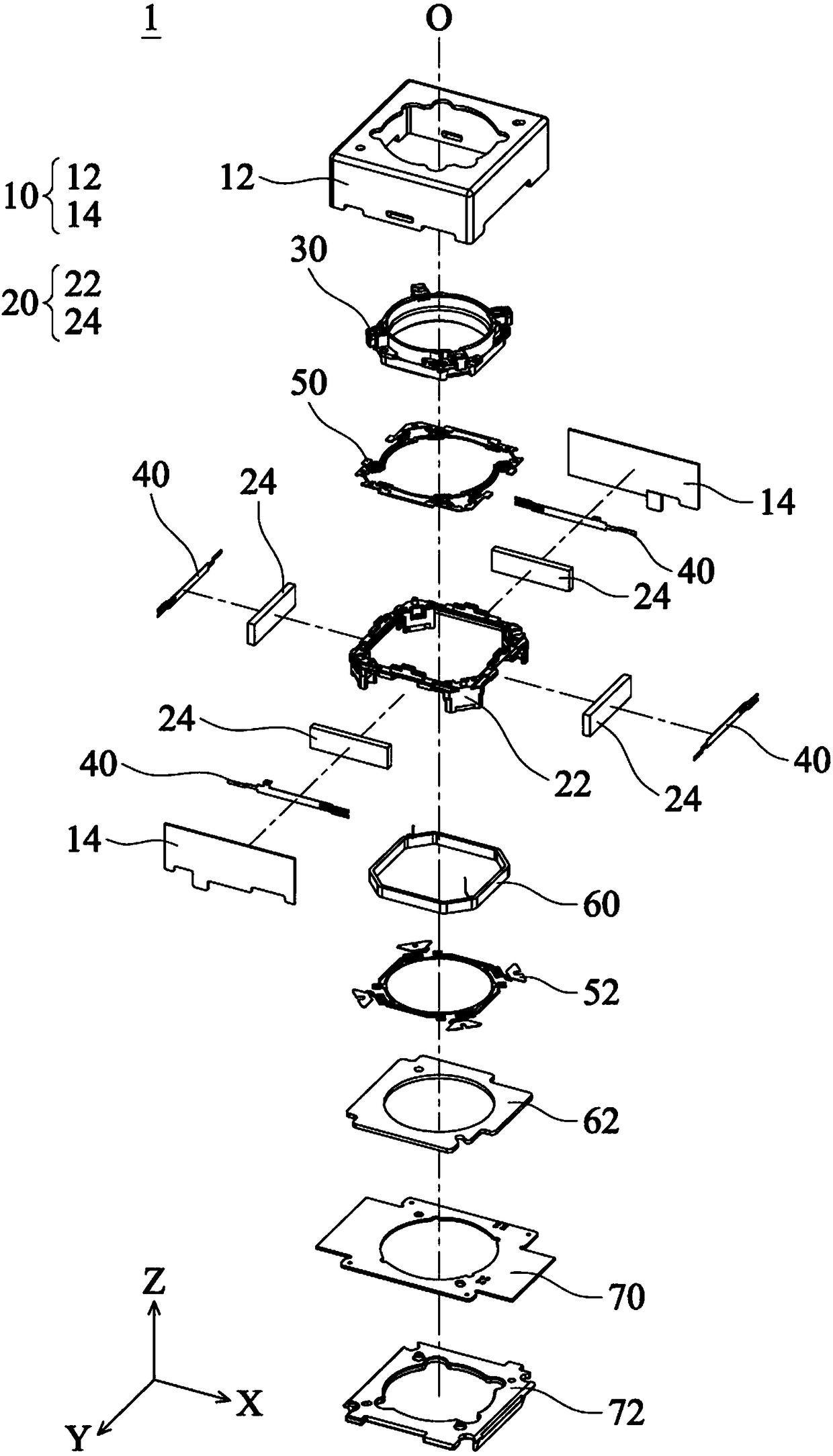
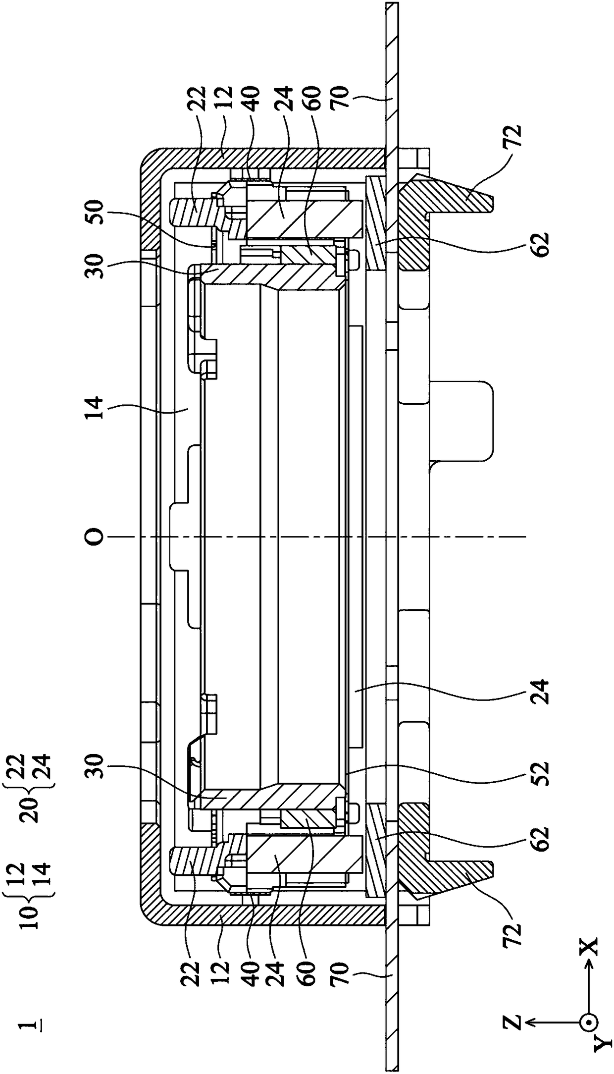
[0057] First please refer to 2A to 2C , the support mechanism 1 of an embodiment of the present invention can be arranged in a camera (or an electronic device with a camera function) to carry a lens, and it can be used to prevent or suppress blurred images captured due to camera vibration. question. Depend on 2A to 2C It can be seen that the aforementioned support m...


PUM


Abstract

A support mechanism for movably supporting a lens, including a fixed module, a movable module, a lens holder and a resilient element. The movable module is movably disposed in the fixed module. The lens holder is movably disposed in the movable module for holding the lens. The resilient element is connected to an outer surface of the movable module and an inner surface of the fixed module, whereinthe outer surface faces the inner surface.

Description

technical field [0001] The invention relates to a support mechanism, in particular to a support mechanism for supporting a lens. Background technique [0002] Generally, cameras, video cameras or mobile phones are often impacted by external forces, causing their internal optical systems to shake, resulting in blurred images. The existing patent document TW I578094 discloses an optical image anti-shock device. After the internal coil is energized, it will interact with the corresponding magnet, so that the lens carrying part that can be fixed with the coil can be along the optical axis direction of the lens and perpendicular to the optical axis direction. Move in the horizontal direction to achieve the effect of Auto Focus (AF) and Optical Image Stabilization (OIS), and then obtain better image quality. However, if figure 1 As shown in the figure, in a general optical image anti-vibration device, the lens is arranged in the lens holder 100, and the lens holder 100 is movabl...

Claims


Application Information

Patent Timeline
IPC IPC(8): G02B7/02G02B7/08G03B5/04
CPCG02B7/023G02B7/026G02B27/646G02B7/08G03B5/04G03B2205/0015G03B2205/0069G02B7/09
Inventor 吴富源周玉珊田口春男
Owner TDK TAIWAN
Why Eureka
Try Eureka