
Cable with cavity

A cavity and cable technology, applied in the direction of insulating cables, cables, circuits, etc., can solve problems such as high voltage, high heat generation, and danger

Inactive Publication Date: 2018-07-31
戴志刚
View PDF2 Cites 1 Cited by
  • Summary
  • Abstract
  • Description
  • Claims
  • Application Information

AI Technical Summary

Problems solved by technology

Most of the cables are erected in the air or installed underground or underwater for telecommunications or power transmission; some existing cables have large current flux and high voltage, so they generate a lot of heat for a long time, which is easy to fatigue the cable structure and packaging materials. It affects the properties of the material, damages the structure of the cable, and is likely to cause danger of spontaneous combustion, and the resistivity of the cable increases with the increase of temperature, which will waste electric energy

Method used


Image

  • Cable with cavity
  • Cable with cavity
  • Cable with cavity

Examples


Embodiment Construction

[0017] Exemplary embodiments of the disclosure will be described in more detail below with reference to the accompanying drawings. Although exemplary embodiments of the disclosure are shown in the drawings, it should be understood that the disclosure may be embodied in various forms and should not be limited to the embodiments set forth herein. Rather, these embodiments are provided for thorough understanding of this disclosure, and for fully conveying the scope of the disclosure to those skilled in the art.

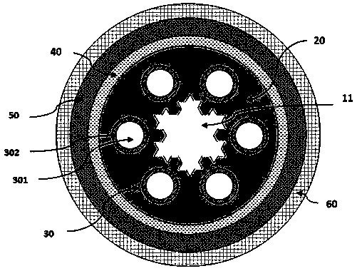
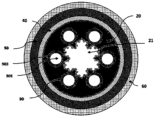
[0018] Such as figure 1 and figure 2 As shown, a cable with a cavity is provided, which sequentially includes from the inside to the outside: cavities 11, 21, a plurality of cable cores 30, an insulating layer 40, a shielding layer 50 and a protective sheath 60, and in the cavity 11, A heat-conducting material 20 is provided between 21 and the insulating layer 40 to enclose a plurality of cable cores 30 therein.

[0019] M cable cores 30 are used in the cable, wherei...


PUM


Abstract

The invention provides a cable with a cavity, and the cable sequentially comprises cavities (11, 21), M cable cores (30), an insulating layer (40), a shielding layer (50) and a protection sleeve layer(60) from the inside to the outside, wherein M is not less than three. A thermal conducting material (20) is disposed between the cavities (11, 21) and the insulating layer (40), and enables the cable cores (30) to be wrapped in the thermal conducting material (20). In a section perpendicular to the length direction of a cable, each of the cavities (11, 21) is a fractal graph shaped like an M-front-end star. The M-front-end star has M acute angles pointing to the outside of the cavities, and M obtuse angles pointing to the inside. Moreover, the perimeter ration of the fractal graph to the M-front-end star is greater than the area ratio of the fractal graph to the M-front-end star. The interior of the cable is provided with the cavities, thereby effectively improving the heat dissipation performances under the condition that the diameter of the cable is not increased, and solving a problem of cable damages caused by the poor heat dissipation. Moreover, the spontaneous combustion risk of the cable can be reduced, and the electric energy waste caused by the increase of the resistivity of the cable with the rise of temperature can be effectively avoided.

Description

technical field [0001] The present application relates to the technical field of electric power transmission, and more specifically, relates to a cable with a cavity. Background technique [0002] Cable is a wire product capable of transmitting electric energy, electric signal and realizing electromagnetic energy conversion, and has a wide range of uses in production and life. A cable can be a rope-like cable made of twisted wires or groups of wires, each wire or group of wires is insulated from each other, and the entire outside is covered with a highly insulating covering. Most of the cables are erected in the air or installed underground or underwater for telecommunications or power transmission; some existing cables have large current flux and high voltage, so they generate a lot of heat for a long time, which is easy to fatigue the cable structure and packaging materials. It affects the properties of the material, damages the cable structure, and easily leads to danger...

Claims


Application Information

Patent Timeline
Patent Type & Authority Applications(China)
IPC IPC(8): H01B7/17H01B7/42
CPCH01B7/17H01B7/423
Inventor 戴志刚
Owner 戴志刚
Learn More