Engine assembly bracket

A technology for assembling brackets and engines, applied in the direction of engine components, machines/engines, assembly machines, etc., can solve problems such as deformation, difficult modules, and unpredictable fixed positions of modules

Active Publication Date: 2021-05-11
SAFRAN AIRCRAFT ENGINES SAS
View PDF8 Cites 0 Cited by
  • Summary
  • Abstract
  • Description
  • Claims
  • Application Information

AI Technical Summary

Problems solved by technology

Their weight then deforms in a significant way when the brackets support them, which makes the module fixing positions unpredictable
[0005] Other disadvantag

Method used


Image

  • Engine assembly bracket
  • Engine assembly bracket
  • Engine assembly bracket

Examples


Embodiment Construction

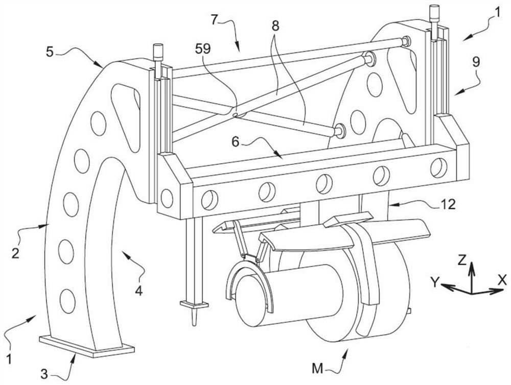
[0030] First refer to figure 1 . The support consists of two similar uprights 1, parallel and substantially vertical, each upright 2 comprising a riser 2 erected from feet 3 on a frame fixed to the ground, inclined away from longitudinal beams 6 for Supports the motor M, which will be described later, in the direction of ascent, over at least a part of its height; the riser 2 also has a curved portion, the concave surface 4 of which is directed towards the motor M assembled on the support, and has an upper arched bend 5 , the upper arched curved portion 5 extends between the rising portion 2 and the vertical surface bearing means for connecting the horizontal beam 6 . This column 1 shape is called a swan neck shape and has a pleasing appearance while providing a simplified cantilever, appropriate rigidity and a small footprint, which is useful for working around the engine and bringing the gear and modules to be installed from various places Provides a lot of freedom. The r...


PUM


Abstract

The assembled stand consists of two parallel columns (1), a vertically movable horizontal beam (6) connecting the tops of the columns, and a swinging tray (17) that moves laterally along the movable beam Mobile and further adapted to rotate around a main axis the motor (M) mounted thereon. The lifting winch (10) is provided with a lifting load sensor to record the total weight of the engine (M). The device advantageously includes trajectory calculation means that integrate structural deformations caused by lifting weights in order to correct the docking trajectory of the modules and ensure their highest accuracy.

Description

[0001] manual technical field [0002] The subject of the present invention is a bracket for assembling an engine, designed more precisely for large rotary engines such as aircraft turbines, without excluding other applications. Background technique [0003] Such engines consist of multiple bulky and heavy modules that must be assembled to each other. The modules arrive at their assembly position on the carriage, are lifted and secured to each other for assembly. Due to the fragility of certain parts of the module, great positioning accuracy and careful handling are required. This is difficult to manufacture on large quantities and heavy parts. Existing assembling brackets seem to be somewhat deficient in this respect. An example is described in document FR2952842A. A bracket for incorporation into a vehicle assembly line is the subject of WO2005 / 014377. [0004] Inaccurate positioning comes from several reasons. Once the module is lifted, the module will first oscilla...

Claims


Application Information

Patent Timeline
IPC IPC(8): F01D25/28B23P21/00B62D65/18B65G47/61
CPCB62D65/18F01D25/285F05D2230/68B23P21/00B25H1/0007
Inventor 斯特凡·安德鲁·鲍彻埃里克·伯斯克莱门特·保罗·克劳德·古诺曼努埃尔·丹尼尔·马丁斯
Owner SAFRAN AIRCRAFT ENGINES SAS
Why Eureka
Try Eureka