Inspection method, inspection device and manufacturing method of intermittent connection type optical fiber ribbon

An inspection method and technology of optical fiber ribbons, which are used in measuring devices, testing of machine/structural components, testing optical fibers/optical waveguide equipment, etc., can solve the problems of laser sensor configuration (difficulty in position adjustment, etc., and achieve the effect of high-precision inspection)

Active Publication Date: 2020-06-16
FUJIKURA LTD
View PDF3 Cites 0 Cited by
  • Summary
  • Abstract
  • Description
  • Claims
  • Application Information

AI Technical Summary

Problems solved by technology

However, if it is considered that a hole for laser irradiation is arranged at each joint (refer to Patent Document 2 Figure 8 ), it is expected that when the number of cores of the optical fiber ribbon increases, the arrangement (position adjustment) of the laser sensor becomes very difficult

Method used


Image

  • Inspection method, inspection device and manufacturing method of intermittent connection type optical fiber ribbon
  • Inspection method, inspection device and manufacturing method of intermittent connection type optical fiber ribbon
  • Inspection method, inspection device and manufacturing method of intermittent connection type optical fiber ribbon

Examples


Embodiment approach

[0039]

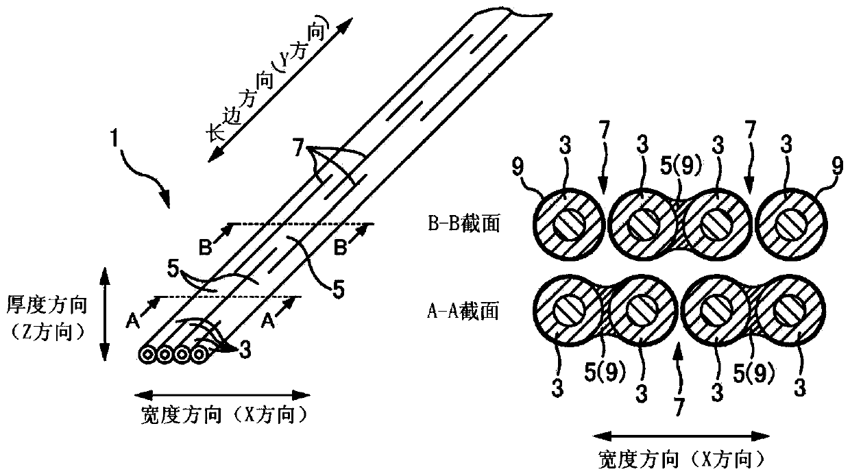
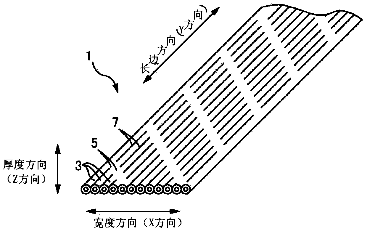
[0040] Figure 1A It is an explanatory diagram of a 4-core intermittent connection type optical fiber ribbon 1 . Figure 1A The right figure is the A-A or B-B sectional view of the perspective view on the left. Figure 1B It is an explanatory diagram of a 12-core intermittent connection type optical fiber ribbon 1 .

[0041] In the description below, if Figure 1A The directions are defined as shown. That is, the direction parallel to the optical fibers 3 constituting the optical fiber ribbon 1 is referred to as the "longitudinal direction". In addition, the direction in which the plurality of optical fibers 3 constituting the optical fiber ribbon 1 is arranged is referred to as a "width direction". In addition, the direction perpendicular to the ribbon surface of the optical fiber ribbon 1 is referred to as "thickness direction".

[0042] The intermittent connection type optical fiber ribbon 1 is an optical fiber ribbon 1 in which a plurality of optical fibers 3...


PUM


Abstract

The present invention provides an inspection method, an inspection device, and a manufacturing method of an intermittent connection type optical fiber ribbon, which can inspect an intermittent connection type optical fiber ribbon with high precision even if the number of cores of the intermittent connection type optical fiber ribbon increases. In the intermittent connection type optical fiber ribbon inspection method of this article, the following operation is performed: while moving the intermittent connection type optical fiber ribbon intermittently arranged at the connecting portion connecting adjacent optical fibers in the longitudinal direction, the optical fiber is repeatedly photographed in the width direction. tape, accumulating the one-dimensional image of the above-mentioned width direction of the above-mentioned optical fiber ribbon; 2D image of .

Description

technical field [0001] The present invention relates to an inspection method, an inspection device and a manufacturing method of an intermittent connection type optical fiber ribbon. Background technique [0002] Patent Documents 1 to 3 describe inspection methods for inspecting optical fiber ribbons in which a plurality of optical fibers are intermittently connected in parallel (hereinafter referred to as "intermittently connected optical fiber ribbons" or simply "optical fiber ribbons"). In the inspection method described in Patent Document 1, the intermittently connected optical fiber ribbon is supported by a guide roller having a stepped portion to separate the non-connected portion of the intermittently connected optical fiber ribbon, and the edge interval, the number of edges, etc. of the intermittently connected optical fiber ribbon are measured. , to detect the abnormality of the connection part of the intermittent connection type optical fiber ribbon. In addition, ...

Claims


Application Information

Patent Timeline
Patent Type & Authority Patents(China)
IPC IPC(8): G01M11/00G01N21/898
CPCG01M11/37G01N21/892G01N21/898G01N2021/8927G02B6/448G01M11/00
Inventor 高桥祐之伊佐地瑞基
Owner FUJIKURA LTD
Why Eureka
Try Eureka