Industrial robot

An industrial and robotic technology, applied in manipulators, scientific instruments, semiconductor/solid-state device manufacturing, etc., can solve the problems of lower resonance frequency, insufficient rigidity of the hand fork, high cost, etc., so as to suppress the generation of defective products and improve the actual The effect of the job rate

Active Publication Date: 2006-07-26
NIDEC SANKYO (ZHEJIANG) CORPORATION +1
View PDF4 Cites 0 Cited by
  • Summary
  • Abstract
  • Description
  • Claims
  • Application Information

AI Technical Summary

Problems solved by technology

Therefore, a large-capacity suction pump must be used, resulting in an increase in the size and cost of the device 100
In addition, the speed of the detection circuit needs to be increased, so the detection circuit is complicated
[0019] However, the above-mentioned hand fork has a square cross section with the same thickness from the base end to the front end. Therefore, sometimes as the size of the workpiece increases, the hand fork becomes longer and the rigidity is insufficient, or the rigidity is sufficient but it is too heavy.
In either case, the resonance frequency is lowered, making it difficult to speed up the entry and exit of the workpiece.

Method used


Image

  • Industrial robot
  • Industrial robot
  • Industrial robot

Examples


Embodiment Construction

[0049] The composition of the present invention will be described in detail below with reference to the preferred embodiments shown in the accompanying drawings.

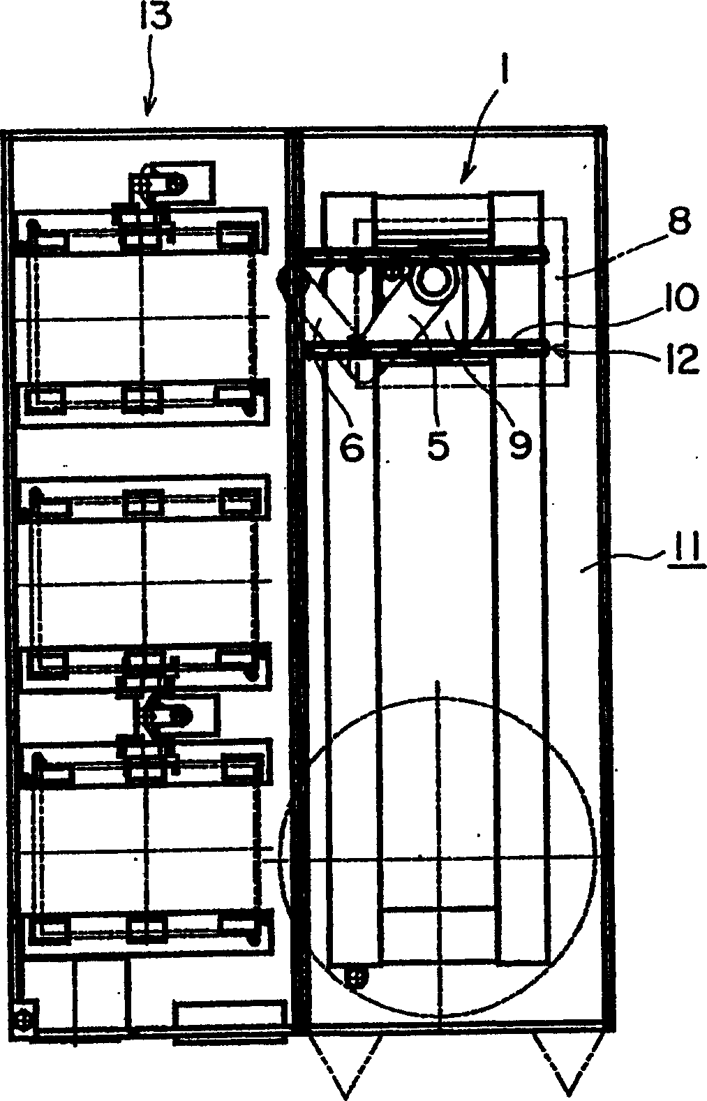
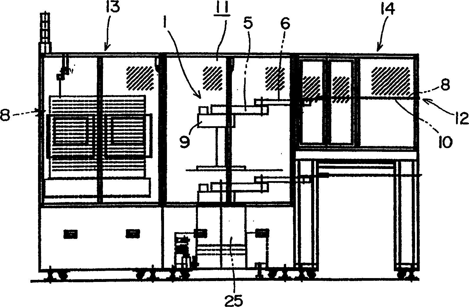
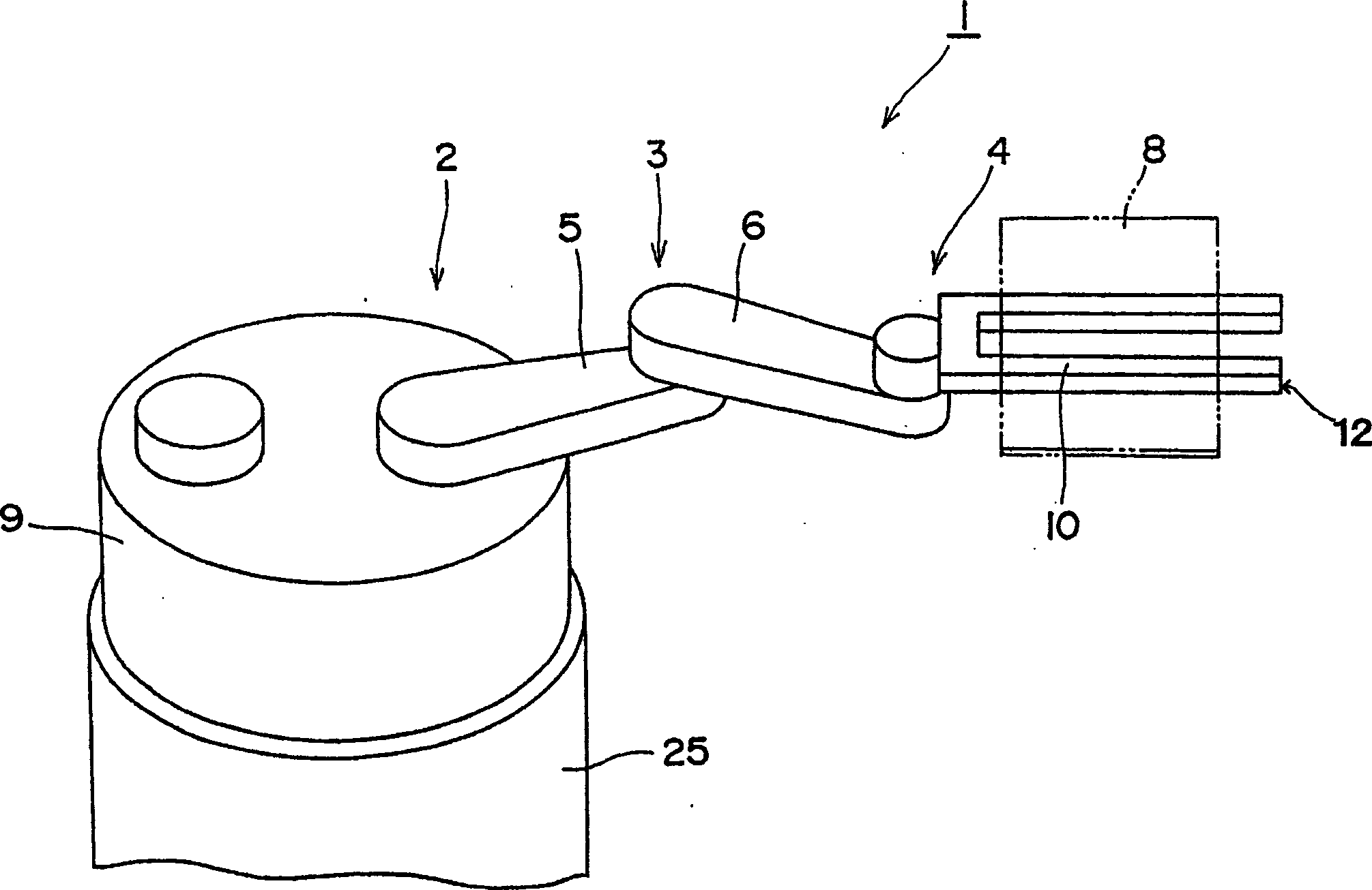
[0050] Figure 1 to Figure 5 Embodiment 1 of the industrial robot 1 of the present invention is shown. This industrial robot 1 performs operations such as assembly, processing, and transportation in the clean space 11 . Further, a particle counter for measuring the cleanliness in the clean space 11 is provided on the hand 10 of the industrial robot 1 . Therefore, the amount of particles near workpieces 8 such as semiconductor wafers and liquid crystal panels placed on the hand 10 can be measured by the particle counter, so accurate inspection can be performed.

[0051] This industrial robot 1 is, for example, an arm drive device that transports the workpiece 8 from the cassette 13 to the manufacturing device 14 . These industrial robots 1, boxes 13, and manufacturing devices 14 are all installed in a clean room 1...


PUM

PropertyMeasurementUnit
thicknessaaaaaaaaaa

Abstract

An industrial robot which works in a clean room can measure the amount of particles of dust and the like in the clean room with high precision and immediate. A light-scattering type particle counter measures the amount of particles in the clean room. The particle counter is provided on a hand portion of the industrial robot and a counter inlet is arranged on the tip of the hand portion. A laser beam used in the particle counter is formed a belt-shaped.

Description

technical field [0001] The present invention relates to an industrial robot, in particular to an industrial robot performing operations such as assembly, processing, and transportation in a clean space. [0002] In addition, the present invention relates to a particle counter applicable to an industrial robot for measuring the number of particles in a gas using light scattering characteristics, and particularly relates to an improvement in the shape of a laser beam irradiated to a sample fluid. Background technique [0003] Such robots include a robot that moves semiconductor wafers or liquid crystal panels from boxes to other devices in a clean room. When handling these semiconductor wafers and liquid crystal panels, the number of particles in the clean room has a great influence on the yield, so there are several methods for inspection. [0004] For example, workers sometimes set up particle counters at defined locations in cleanrooms for periodic inspections. In additio...

Claims


Application Information

Patent Timeline
Patent Type & Authority Patents(China)
IPC IPC(8): B25J11/00G01N15/14
CPCB25J15/0014G01N21/47H01L21/68
Inventor 矢泽隆之常田晴弘安川员仁吉泽丰近藤秀幸中岛弘登永泽芳水
Owner NIDEC SANKYO (ZHEJIANG) CORPORATION
Why Eureka
Try Eureka