Belt for measuring the temperature of an object

A technology for objects and temperature sensors, applied to parts of thermometers, thermometers, measuring devices, etc., can solve problems such as difficulty in obtaining administrative licenses, complicated technical documents, etc., and achieve good measurement accuracy

Active Publication Date: 2018-07-31
ELECTRICITE DE FRANCE
6 Cites 1 Cited by

AI-Extracted Technical Summary

Problems solved by technology

This type of meter is accompanied by very complex technical documentation and difficult to obtain administrative licenses
[0014] Furthermore, the implementation of systems for positionin...

Method used

[0078] The spring 71 makes it possible to apply a pressure designed to press the lower part 510 of the thermocouple against the object OBJ in order to ensure a satisfactory contact. The lower surface 61 may include grooves that ensure the positioning of the lower section 510 of the thermocouple and avoid the formation of air gaps.
[0090] The temperature sensor 5, wh...

Abstract

The invention relates to a belt for measuring the temperature of an object, the belt including: at least one temperature sensor (5); a strap (10) having a circumference intended to encircle the object; and a device (20) for tightening the strap (10) around the object, characterized in that the temperature sensor (5) is mounted on an individual thermally insulating carrier (6) that is guided in a guiding direction (62) toward the object (OBJ) between at least two thermally insulating runners (31, 32) that bear against the object, the runners (31, 32) being fastened to the strap (10).

Application Domain

Thermometer detailsNuclear energy generation +3

Technology Topic

Mechanical engineering

Image

  • Belt for measuring the temperature of an object
  • Belt for measuring the temperature of an object
  • Belt for measuring the temperature of an object

Examples

  • Experimental program(1)

Example Embodiment

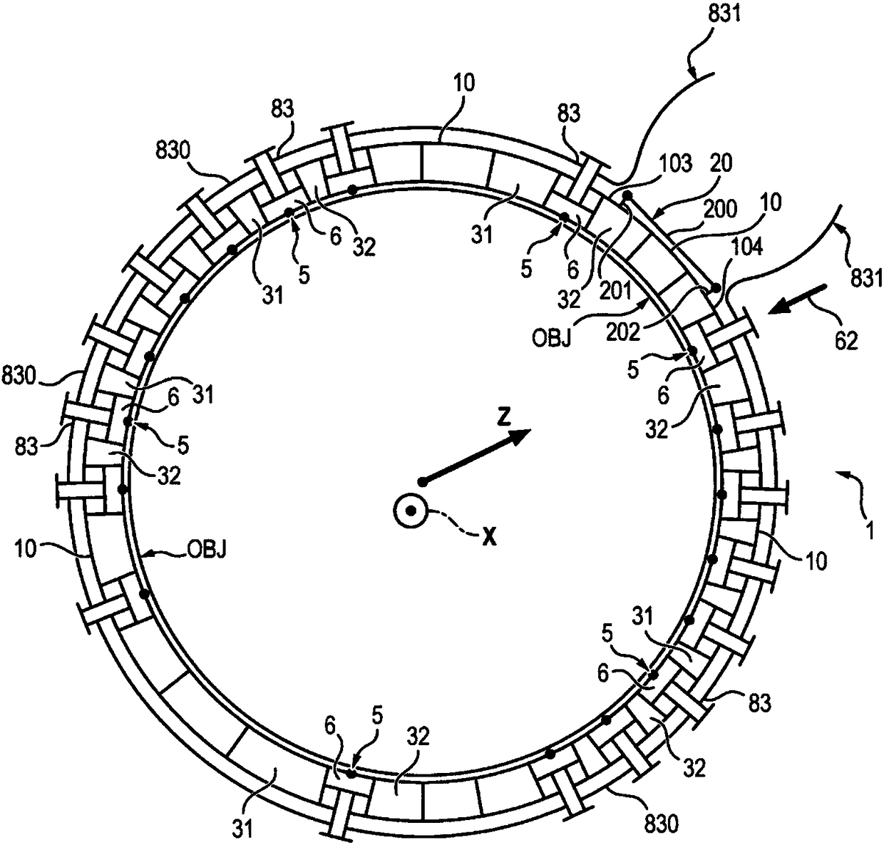
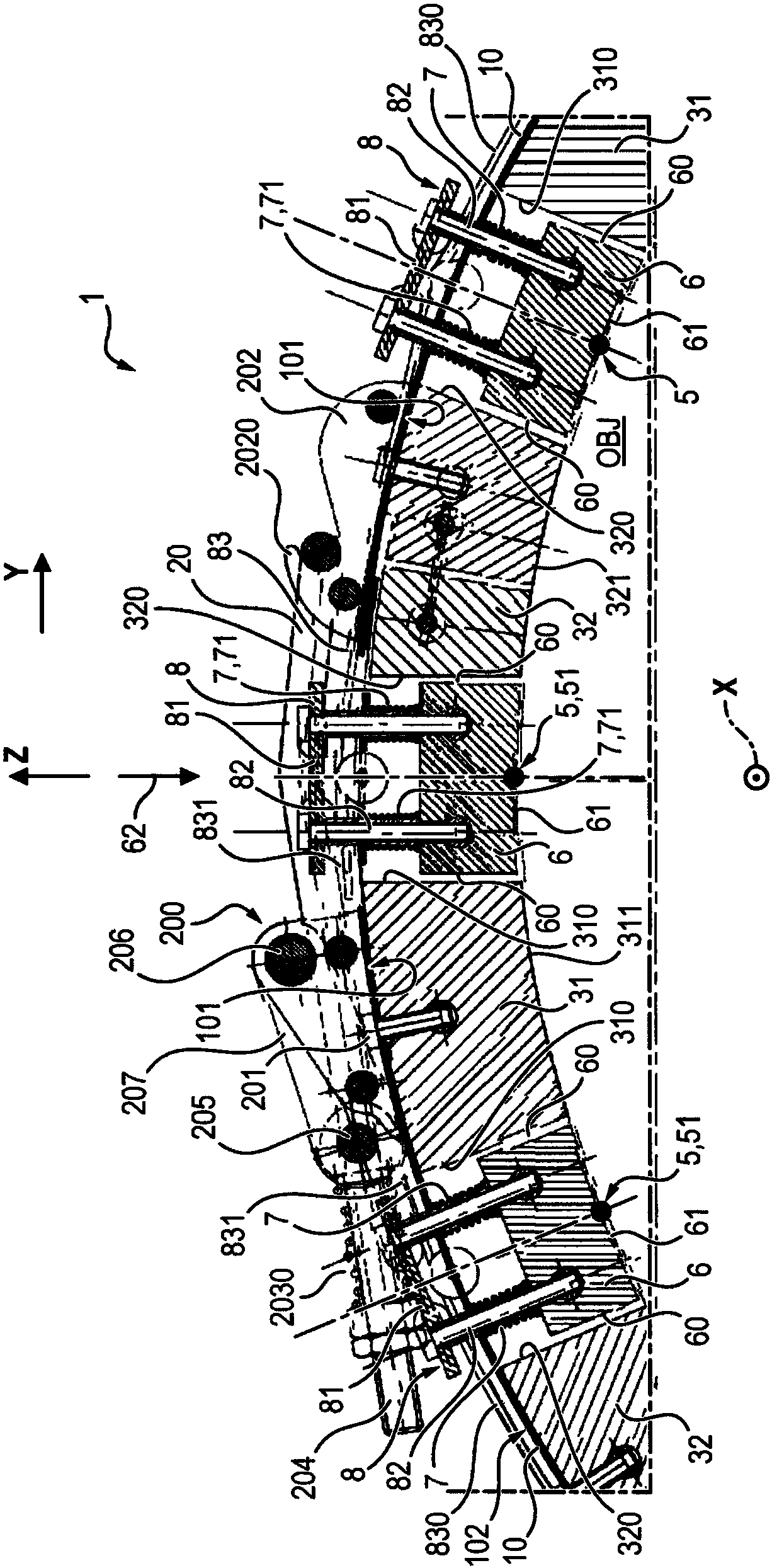
[0046]In the figures, a measuring tape 1 according to the invention is used for attaching at least one sensor 5 on an object OBJ. As described below, the object OBJ may eg be a fluid conduit OBJ such as eg a water pipe. One application of the invention is a belt for mechanically attaching one or more sensors 5 to a liquid or gas pipe as an object OBJ. The object OBJ is, for example, a water pipe of the main circuit of a pressurized water reactor (PWR) of a power station. The water pipe may be a high pressure pipe. The belt includes one or more temperature sensors 5 . Of course, the belt 1 may additionally comprise one or more sensors other than the temperature sensor 5 or only one or more temperature sensors 5 .
[0047] The belt 1 comprises a strip 10 having a perimeter for encircling an object OBJ such as for example a pipe.
[0048] In the figure, the object OBJ extends along the axial direction X, around which the strips 1 must be arranged. The strips 10 of the strip 1 thus encircle the object OBJ in a plane transverse to the direction X formed by the directions Z and Y perpendicular to each other and to the direction X. The direction Z starts from the axis X of the object OBJ and passes through the object OBJ towards the belt for wrapping the object OBJ around this axis X. The direction Y is the direction around the object OBJ and around the axis X tangent to the circumference of the strip 10 . The strip 10 is, for example, a strip made of metal.
[0049] The object OBJ or pipe OBJ for example has an outer cylindrical profile, for example circular. For example, in the case of a cylindrical object OBJ around the axis X, the direction Z is the radial centrifugal direction starting from the object OBJ from the inside to the outside with respect to the belt 1 . The object OBJ or pipe OBJ may have a metallic outer surface, eg made of steel, against which the band 1 is arranged. Of course, the invention can be applied to any type of object, in particular cylindrical around the direction X, which has to be surrounded by the belt 1, which can be other than the objects mentioned above, such as for example thermodynamic systems, agricultural Food, petrochemical, methanation units.
[0050] Belt 1 comprises at least one temperature sensor 5 . For example, in figure 1 Among them, a plurality of temperature sensors 5 are provided on the belt 1 . The or each temperature sensor 5 comprises, for example, a thermocouple.
[0051] The measuring tape 1 also comprises clamping means 20 for clamping the strip 10 around the object OBJ. The clamping device 20 allows for example to fasten the strip 10 around the object OBJ.
[0052] According to one embodiment, the temperature sensor 5 is part of the measuring chain. figure 1 These elements and the interfaces between the measurement chain and external elements are shown. The first interface is for example formed by the outer surface SUR of the object OBJ, to which the sensor has to be attached by means of the strap 1 . The temperature sensor 5 is used to convert a physical quantity G or measurand G into a usable (usually electrical) signal S. The controller COND converts the quantity S at the output of the sensor 5 into a voltage whose amplitude or frequency reflects the time evolution of the physical quantity G. The first interface SUR constitutes the boundary between the physical process and the desired information. The ability of the sensor 5 to measure temperature may be affected by factors pertaining to the environment (corrosion, geometric irregularities, humidity, etc.), especially for sensors in direct contact.
[0053] In certain applications (eg measurements by fastening to pipes) there is another factor which is indispensable for the correct operation of the instrument chain. This is the mechanical attachment system 1 of the sensor 5 whose main role is to support the sensor 5 and keep it in contact with the part desired to be measured (usually a pipe), allowing the chain to continue to provide the desired function: the measurement of a physical quantity. To ensure correct operation of the sensor 5, the attachment system 1 must also shield it from any perturbations inherent in the process but undesirable for the measurement (eg vibrations, thermal and mechanical constraints, etc.).
[0054] In the case of pressurized water reactors (PWRs), strict observation of the quality goals to be achieved is indispensable. This is especially the case for machinery resistance to stress (primary, secondary and auxiliary circuits) already defined by design and construction rules (DCR-M for machinery). For any mechanical equipment not subjected to DCR, such as for example the system 1 for attaching the temperature sensor 5, a qualification process must be carried out to ensure the metrological performance of the meter chain (functional qualification). With respect to mechanical attachment systems 1 there are no specific design and manufacturing standards, but qualification tests must verify their security with respect to the components on which they are to be mounted.
[0055] During qualification, conditions such as resistance to earthquakes, pressure, temperature or humidity can be verified.
[0056] In addition to the situations required during qualification, when such an attachment system 1 is permanently installed there, other specific situations of the main circuit of the PWR have to be considered:
[0057] - The average temperature in operation is 300°C and is below 70°C during shutdown.
[0058] - Radiation at full power is 5kGy/year (or 100000Gy for 20 years).
[0059] The first case above has implications for the choice of material as well as the design of the attachment system 1 . The system 1 for attaching the sensor 5 must be designed to resist strong mechanical stresses while still maintaining its primary function. Regarding the second case, which plays an implicit role in the choice of material, but the main effect of radiation on the design of the system 1 for attaching the sensor 5 is the Intervention time required for any maintenance operations on the system 1 itself.
[0060] One application of the invention is the mechanical attachment strap 1 of a temperature sensor 5 against a water pipe OBJ of the main circuit of a pressurized water nuclear reactor of a power station.
[0061] According to the invention, the temperature sensor 5 is mounted on a separate thermally insulating support 6 . The independent thermally insulating support 6 is guided along the guiding direction 62 between at least two thermally insulating pads 31 , 32 attached to the sheet strip 10 towards the object OBJ. The thermal insulation pads 31 , 32 are intended to abut against the object OBJ and comprise inner surfaces 311 , 321 for contact with the object OBJ. The inner surfaces 311, 321 may have a shape complementary to the shape of the object OBJ, for example cylindrical with the same diameter as the cylindrical object OBJ.
[0062] According to one embodiment, the individual thermally insulating supports 6 have a thermal conductivity lower than that of the strips 10 and/or lower than that of the object OBJ or lower than that of steel. According to one embodiment, the independent thermally insulating support 6 is made of a material having a thermal conductivity greater than or equal to 0.15 W/mK and less than or equal to 0.40 W/mK, for example at 500°C. Thus, according to one embodiment, the independent thermally insulating support 6 may be made of compressed calcium silicate, for example MonoluX 500 (registered trademark), a material having a thermal conductivity of 0.20 W/mK at 500°C. In another embodiment, the independent thermal insulation support 6 may be made of polymer resin material or other materials. According to one embodiment, the independent thermally insulating support 6 does not contain halogens in order to be suitable for use in a nuclear environment (PWR or otherwise) as described above. According to one embodiment, the thermally insulating pads 31 , 32 have a thermal conductivity lower than that of the strip 10 and/or lower than that of the object OBJ or lower than that of steel. According to one embodiment, the heat insulating pads 31 , 32 are made of a material having a thermal conductivity greater than or equal to 0.15 W/mK and less than or equal to 0.40 W/mK, for example at 500°C. Thus, according to one embodiment, the thermally insulating pads 31 , 32 may be made of compressed calcium silicate, for example MonoluX 500, a material having a thermal conductivity of 0.20 W/mK at 500°C. In another embodiment, the thermal insulation pads 31, 32 may be made of polymer resin material or other materials. According to one embodiment, the material of the thermally insulating pads 31 , 32 does not contain halogens in order to be suitable for use in a nuclear environment (PWR or otherwise) as described above.
[0063] In the case of several temperature sensors 5 distributed along the periphery of the strip 10 , each temperature sensor 5 is mounted on its respective independent thermally insulating support 6 . Each thermally insulating support 6 is guided along their appropriate guiding direction 62 between the thermally insulating pads 31 , 32 attached to the strip 10 towards the object OBJ.
[0064] For example, for an object OBJ with a curved convex outer surface which has to be surrounded by the periphery of the strip 10 , the guiding direction 62 is radial. For example, in the case of a cylindrical object OBJ surrounded by the band 1 , the guiding direction 62 points in a centripetal direction opposite to the direction Z.
[0065] According to one embodiment, limiting means 7 are installed between the support 6 and the strip 10 to limit the movement of the support 6 along the guiding direction 62 towards the object OBJ.
[0066] Thereby, the support 6 and the temperature sensor 5 are guided concentrically towards the object OBJ.
[0067] For example, each pad 31 , 32 comprises a side surface 310 or 320 positioned facing the side surface 60 of the support 6 . Surfaces 310 and/or 320 and/or surface 60 are, for example, substantially radial. The support 6 is positioned between the guide surfaces 310 and 320 .
[0068] Furthermore, according to one embodiment, the temperature sensor 5 comprises a portion 51 for being arranged against the object OBJ. This portion 51 is arranged on an inner surface 61 of the support 6 and is intended to turn towards the object OBJ.
[0069] According to one embodiment, the pad 6 is attached to the inner surface 101 of the strip 10 .
[0070] According to one embodiment, means 8 for lifting the support 6 in a direction opposite to the guiding direction 62 towards the object are provided for lifting the support 6 such that in the first high position the sensor 5 is not in contact with the object OBJ , and the pads 31 and 32 are in contact with the object OBJ.
[0071] Thus, according to one embodiment, the means 8 for lifting the support 6 can assume a first high position in which the sensor 5 is located at a non-zero distance from the object OBJ along the guiding direction 62 . The lifting device 8 can be moved to a second lower position, in which the sensor 5 is arranged next to the object OBL. The lifting means 8 are actuatable from the outside to move the sensor 5 from the first position to the second position, the limiting means 7 allow the support 6 and thus the sensor 5 to be defined so as to position itself along the guiding direction 62 towards the object OBJ from the first position to the second position. The first position drops to the second position.
[0072] The invention allows to ensure high Accuracy class and very short response time. On the object OBJ, at positions predetermined according to the phenomenon to be measured, temperature sensors 5 and separate thermal insulation means 7 for applying pressure are provided in order to ensure satisfactory contact of each temperature sensor 5 with the object OBJ. The general configuration of the band is specially adapted to the diameter of each available part of the object OBJ or pipe OBJ, the application range of the band 1 may extend from 4 inches to several hundreds of inches. In the case of a large diameter object OBJ, relying on several parts of the belt 1 joined together allows to ensure that the belt 1 is well held at all points of the perimeter, the positioning pads 31, 32 of the belt 1 allow the Provide spacing. The strips 1 are thus designed for quick installation (less than 2 minutes per strip) and can be used up to 500°C depending on the thermal insulation material used in the support 6 and pads 31, 32 and depending on the nature of the thermocouple 5 , 800°C, or even 1000°C. The strip 1 may carry one or more temperature sensors 5, the density of which may extend along the perimeter of the strip 10 up to approximately one temperature sensor 5 every 40 mm.
[0073] Band 1 considers constraints related to the nuclear environment (ionizing radiation) and all other constraints belonging to industrial installations, such as volume, compatibility of materials, mechanical resistance of the system to earthquakes.
[0074]According to one embodiment, the means 8 for lifting the thermally insulating support 6 comprise an upper plate 81 attached to the support 6 by means of at least one rod 82 passing through the hole 102 of the strip 10 . The plate 81 is located outside the strip 10 , ie oriented along the direction Z above the strip.
[0075] According to one embodiment, the limiting means 7 comprise one or more springs 71 mounted between the support 6 and the strip 10 . The spring 71 is, for example, a compression spring. The spring constrains the support 6 to lower itself in the guiding direction 62 towards the object OBJ. Spring 71 is, for example, a coil spring surrounding rod 82 . A washer 824 may be provided between the spring 71 and the upper surface 63 . The rod 82 can be formed by a screw, for example. The rod 82 comprises: a first lower end 821 attached to the upper surface 63 of the support 6 , for example by screwing into this upper surface 63 ; a second upper end 822 attached to the plate 81 ; and an intermediate section 823 extending between the lower end 821 and the upper end 822 and passing through the hole 102 of the strip 10 . The upper surface 63 of the support 6 is located at a distance from its lower surface 61 on which the portion 51 of the temperature sensor 5 is positioned.
[0076] The temperature sensor 5 may have a U shape when formed of a thermocouple. When the temperature sensor 5 is formed by a thermocouple, the temperature sensor 5 comprises a first lower section 510 extending or having a portion along the axial direction X, the lower section 510 forming a resistance Part 51 arranged by object OBJ. This lower section 510 of the thermocouple is connected to a transverse section 52 which extends along and at a distance from the transverse surface 64 of the support 6 in order to connect to The upper section 53 of the cavity 66 of the member 6 extends from the transverse surface 64 to the other transverse surface 65 of the support 6 so as to leave this surface 65 again. Segment 52 extends, for example, along direction Z, pointing away from object OBJ. The lateral surfaces 64 and 65 are located at a distance from each other and are connected at their upper end to the upper surface 63 and at their lower end to the lower surface 61 , the support 6 can be a parallelepiped.
[0077] The upper segment 53 is connected to an outer segment 54 which extends away from the lateral surface 65, under and beyond the strip 10, so as to be accessible from the outside and to be able to connect to the sensor for external acquisition and processing performed by the sensor 5. The unit of measurement (eg regulator COND and/or others).
[0078] The spring 71 makes it possible to apply a pressure designed to press the lower part 510 of the thermocouple against the object OBJ in order to ensure a satisfactory contact. The lower surface 61 may include grooves that ensure the positioning of the lower section 510 of the thermocouple and avoid the formation of air gaps.
[0079] According to one embodiment, the lifting device 8 of the support 6 comprises means 83 for maintaining the support 6 in the first high position. A holding member 83 is removably attached to the upper plate 81 . When the retaining member 83 is removed from the plate 81 , the limiting means 7 cause the support 6 and thus the sensor 5 to move from a first high position to a second low position.
[0080] According to one embodiment, the holding members 83 respectively associated with the respective supports 6 for the different temperature sensors 5 are integral with each other. In the embodiment shown in the figures, the holding member 83 is formed by a cable 830 , for example a metal cable, which passes through a guide 84 attached to the plate 81 to keep the support 6 in the first high position. The cable 830 includes one or two portions 831 positioned outside the plate 81 to allow removal of the cable 830 from the guide 84 to lower the sensor 5 from the first position to the second position. Thereby, the portion 831 is positioned outside the strip 10 and is accessible from the outside to serve as a gripping portion to pull on the cable 830 to remove it. The cable 830 thus allows all temperature sensors 5 to be moved from the first high position to the second low position by a single retraction action of this cable 830 .
[0081] According to one embodiment, the guide 84 has one or more pulleys 841 , 842 and 843 . The guide 84 comprises, for example, at least two pulleys 841 , 842 , 843 rotatably mounted relative to the plate 83 , and the cable 830 is guided between these pulleys. For example, at least one first upper pulley 841 and/or 842 and at least one second lower pulley 843 are provided, and the cable 830 is pulled between the first pulley 841 and/or 842 on the one hand and the second pulley 843 on the other hand. guide. The pulley 841 is rotatably mounted about a rotation axis 8410 extending eg along the axial direction X and is attached to the plate 81 , eg directly on, under or in the plate. The pulley 842 is rotatably mounted about a rotation axis 8420 extending eg along the axial direction X and is attached to the plate 81 , eg directly on, under or in the plate. The pulley 841 is at a distance from the pulley 842 along the tangential direction Y. Plate 81 may include openings 810 to allow passage of pulleys 841 and/or 842 . The second pulley 843 is rotatably mounted around a second axis of rotation 8430 located at a distance from the lower surface 811 of the plate 81 . A second pulley 8430 is for example positioned between the plate 81 and the support 6, the second axis of rotation 8430 is attached to the arm 812 attached below the surface 811 of the plate. The axis 8430 extends, for example, along the axial direction X and is positioned between the axes 8410 and 8420 along the tangential direction Y.
[0082] Due to the fact that the support 6 of the sensor 5 remains in the second highest position during installation of the band 1 around the object, the invention makes it possible to place the temperature sensor 5 in contact against the object OBJ during this installation. Damage to the temperature sensor 5 due to friction against the surface of the object OBJ is thereby avoided. When the strap is mounted and secured around the object OBJ by its clamping means 20, the retaining member 83 is withdrawn, which causes the support 6 to move from the second high position to the first low position. The temperature sensor 5 is thus supported against the object OBJ, since the support 6 is guided along the direction 62, there is no risk of the temperature sensor moving sideways relative to the object.
[0083] The strip 10 is, for example, metallic and can be made of stainless steel sheet. The length of the strip 10 may be cut to fit the perimeter of the object OBJ or pipe OBJ. The strip 10 is configured to tolerate changes in temperature (and thus mechanical stress) such as pertaining to high pressure piping OBJ (eg the main circuit of a pressurized water reactor). The strip 10 comprises holes for attaching the pads 31 , 32 against its lower surface 101 . Thermally insulating pads 31 , 32 are attached below the strip 10 and ensure the positioning of the strip 1 on the object OBJ and thermal insulation relative to the object OBJ. The clamping device 20 is attached to the outer surface 102 of the strip 10 .
[0084] According to one embodiment, the clamping device 20 comprises a mechanical assembly 203 for elastic attachment between at least two mechanical parts 201 and 202 attached to the two ends 103 and 202 of the strip 10 respectively. 104. In particular, the clamping device 20 may be of the type having a hook between the two parts 201 and 202 .
[0085] As described below, the mechanical assembly 203 is, for example, of the hinge clamp type, which may include one or more springs 2030 . The elasticity of the mechanical attachment assembly 203 ensures the positioning of the band 1 on the object or pipe OBJ over the entire range of dimensions defined by the standards governing the supply of industrial pipes and other boiler manufacturing elements. The strap 1 is thus elastically attached to the object OBJ. The clamping device 20 ensures elastic retention on the object OBJ against differential expansion and vibrations.
[0086] According to one embodiment, the mechanical assembly 203 of the clamping device 20 comprises for example a rod 204 articulated via a first articulation axis 205 to a connecting rod part 207 which itself is articulated to the first part 201 via a second articulation axis 206 . The hinge shaft 205 is mounted on a yoke 208 slidably mounted on the rod 204 . A compression spring 2030 is provided between the abutment 209 attached to the rod 204 and the yoke 208 . The abutment 209 may be formed by one or more nuts screwed onto the threads of the rod 204 . The rod 204 is for example stirrup-shaped and comprises two parallel branches 2041 and 2042 passing through the ends of the branches 2041 and 2042 located at a distance from their ends near where the abutment 209 is located) The third hook branches 2043 are connected to each other. The second part 202 for example comprises a second hook member 2020 for cooperating with a first hook member 2043 along the tangential direction Y at the clamping position of the strip 10 around the object OBJ. The hook member 202 for example comprises two hooks 2021 and 2022 remote from each other along the axial direction X, against which the member 2043 is captured by extending between these hooks 2021 and 2022 in the clamping position of the strap 1 . The portion of hook branch 2043 positioned between hooks 2021 and 2022 serves as a gripping handle for rod 204 . To release rod 204 , the user pulls on part 2043 in direction Y to bring abutment 209 closer to yoke 208 , which compresses spring 2030 until it moves hook part 2043 behind hook part 202 . The user then lifts the lever 204 so that it rotates about its axis 205, thereby opening the mechanical assembly 203 into position for unwinding the strap 1 .
[0087] The temperature measuring strip according to the invention allows a large number of measuring points to be carried out simultaneously within a few minutes while still ensuring their geometric positioning. An example is the manufacture of pipe of a diameter which can be positioned over the full range of standard governing dimensional tolerances. The positioning of the sensor 5 and of the outlet 54 of the cable of the temperature sensor 5 during manufacture allows to ensure the absence of any positioning errors and any ambiguous markings in the application of the implementation procedure. The recommendations made regarding packaging allow limiting the surface and the risk of radiation or chemical contamination.
[0088] The strap is lightweight and elastically attached to the object 1 and each sensor 5 has an independent system 6 for applying pressure coupled to thermal insulators 31, 32, the strap 1 ensures a good connection between the sensor 5 and the object OBJ contact regardless of temperature changes (causing expansion and thus mechanical stress), vibrations or clamping torques on the object OBJ. Belt 1 is safe for the object OBJ and the facility in which the object OBJ is located.
[0089] During maintenance shutdowns of the equipment, for example during radiographic operations in the case of fluid lines of the PWR, the disassembly and reassembly of the belt 1 is rapid and the lifting means 8 and limiting means for contact with the support 6 of the sensor 5 Repositioning of 7 is easy and fast.
[0090] The temperature sensor 5 , which is individually contacted and thermally insulated by the independent support 6 , has an optimum response time and very good measurement accuracy without common mode effects.
[0091] According to one embodiment, the strip 1 may be covered by a thermal insulation pad 300 . The thermally insulating pad 300 has an inner cutout 301 corresponding to the contour of the belt 1 (for example, in nuclear applications). The pad 300 is for example made of a solid material or a material that keeps its shape around the belt 1 and around the object OBJ. For example, the pad 300 is formed by two half cylinders 302 arranged on either side of the band 1 mounted on the object OBJ so as to encircle them around the axial direction X.
[0092] Without increasing the external volume of the thermally insulating pad 300 , it is possible to use a measuring tape 1 having a small thickness and having thermal insulators 31 , 32 in contact with the object OBJ.
[0093] The clamping device offers the advantage of being adaptable to a wide range of object diameters and strip lengths and to all cylindrical objects (pipes, pressurizers, steam generators, reactors, exchangers, water pipes).
[0094] The measuring tape according to the invention offers the advantage of being able to install a large number of temperature sensors very quickly around an object OBJ located in a defined environment (such as, for example, in the protective shell of a nuclear reactor subjected to ionizing radiation, for which the operator must This is particularly attractive in situations where exposure to as little of this radiation as possible is involved for the shortest possible duration). The invention also allows the installation of a large number of temperature sensors with high reliability in these defined environments.
[0095] The invention allows the temperature sensors to be in direct contact with the object OBJ, which allows optimizing the temperature measurement accuracy and reducing their response time.

PUM

no PUM

Description & Claims & Application Information

We can also present the details of the Description, Claims and Application information to help users get a comprehensive understanding of the technical details of the patent, such as background art, summary of invention, brief description of drawings, description of embodiments, and other original content. On the other hand, users can also determine the specific scope of protection of the technology through the list of claims; as well as understand the changes in the life cycle of the technology with the presentation of the patent timeline. Login to view more.

Similar technology patents

Spindle deformation analysis device

InactiveCN105115729Agood measurement accuracy
Owner:API ZC PRECISION INSTUMENT CO LTD

Kit for diagnosis and detection of total protein by using potassium hydroxide method

InactiveCN107525774Agood measurement accuracyhigh precision
Owner:BIOBASE BIODUSTRY (SHANDONG) CO LTD

Linear testing device for variable-density optical filter

PendingCN112284689AImprove test efficiencygood measurement accuracy
Owner:SHENYANG ACAD OF INSTR SCI

Positioning method for pattern-free silicon chip measurement

ActiveCN104979257Agood measurement accuracyImprove measurement repeatability
Owner:RAINTREE SCI INSTR SHANGHAI

Classification and recommendation of technical efficacy words

  • good measurement accuracy

Grinding wheel wear online monitoring method

InactiveCN106078508Agood measurement accuracy
Owner:CHANGCHUN UNIV OF TECH

Wireless equipment test system

ActiveCN105515692Agood measurement accuracy
Owner:GENERAL TEST SYST

Measuring device and measuring method for measuring the power of a high-frequency signal

ActiveUS20090189593A1good measurement accuracy
Owner:ROHDE & SCHWARZ GMBH & CO KG

Protective Rogowski coil current transformer based on combined integral

InactiveCN105738676AGood measurement accuracyMeet error requirements
Owner:NANJING INST OF TECH

Total bilirubin (oxidization method) detection kit adopting sodium nitrite method

ActiveCN106814037Agood measurement accuracyhigh precision
Owner:BIOBASE BIODUSTRY (SHANDONG) CO LTD
Why Eureka
Try Eureka