
Linear testing device for variable-density optical filter

A testing device and filter technology, which is applied to measurement devices, optical instrument testing, and optical performance testing, etc., can solve the problems of low linear testing efficiency, no filter movement, low efficiency, etc., so as to facilitate subsequent processing. The effect of ideal processing and measurement accuracy and high test efficiency

Pending Publication Date: 2021-01-29
SHENYANG ACAD OF INSTR SCI
View PDF6 Cites 0 Cited by
  • Summary
  • Abstract
  • Description
  • Claims
  • Application Information

AI Technical Summary

Problems solved by technology

Due to the large beam spot of the spectrophotometer, there are generally fewer points that can be measured, and the accuracy of the measurement results is low; while the small size filter cannot be measured, so it cannot be produced.
In addition, there is no precise mechanism for the equal division movement of the filter, and it is indexed by printing paper tape, so the positioning during measurement is not very accurate.
During the linearity test, the inspector has to repeatedly move the filter and record the measurement data. After several rounds, it is easy to make mistakes.
Under such circumstances, it is very inefficient to conduct a linearity test for as little as 30 minutes and as long as 1 hour.
Due to the low efficiency of linearity testing, when variable density filters are mass-produced, the linearity can only be tested in a small number of samples, and there is a risk of unqualified products leaving the factory.
In recent years, the output of variable density filters has been increasing, and there are more and more types, and the low-efficiency linearity test is increasingly affecting the production of products

Method used


Image

  • Linear testing device for variable-density optical filter
  • Linear testing device for variable-density optical filter
  • Linear testing device for variable-density optical filter

Examples


Embodiment Construction

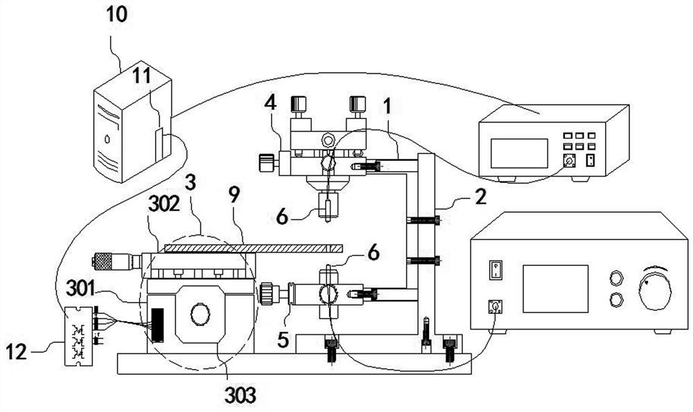
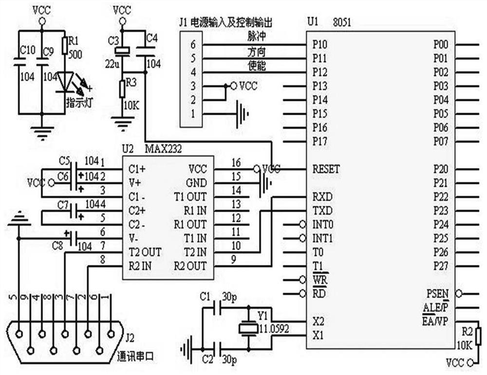
[0016] As shown in the figure, the variable density filter linear test device includes an inclination adjustment arm 1, an optical path support frame 2, a mobile platform 3, a four-axis optical fiber adjustment frame 4 and a two-axis optical fiber adjustment frame 5; the mobile platform 3 includes Y An axis translation unit 301 and an X-axis fine-tuning unit 302; the four-axis optical fiber adjustment frame 4 and the two-axis optical fiber adjustment frame 5 are respectively fixed at the upper and lower ends of the inclination adjustment arm 1; the optical fibers on the four-axis optical fiber adjustment frame 4 The optical fiber collimator 6 is respectively fixed at the optical fiber detection port of the light source and the two-axis optical fiber adjustment frame 5; The column of the arm 1 is fixedly connected with the optical path support frame 2; the Y-axis translation unit 301 includes a fine-tuning unit body, a computer 10, a single-chip microcomputer control board 11, a...


PUM


Abstract

The invention belongs to the field of density filter testing, and particularly relates to a linear testing device for a variable density optical filter. The device comprises an inclination angle adjusting arm (1), an optical path supporting frame (2), a moving platform (3), a four-axis optical fiber adjusting frame (4) and a two-axis optical fiber adjusting frame (5). The moving platform (3) comprises a Y-axis translation unit (301) and an X-axis fine adjustment unit (302); the four-axis optical fiber adjusting frame (4) and the two-axis optical fiber adjusting frame (5) are fixedly located atthe upper end and the lower end of the inclination angle adjusting arm (1) respectively; optical fiber collimators (6) are fixedly arranged at an optical fiber light source of the four-axis optical fiber adjusting frame (4) and an optical fiber detection port of the two-axis optical fiber adjusting frame (5) respectively; and the Y-axis translation unit (301) comprises a fine adjustment unit body, a computer (10), a single-chip microcomputer control panel (11), a stepping motor driving module (12) and a stepping motor (303). The device is high in test efficiency, ideal in measurement precision and wide in application, and samples do not need to be accurately placed.

Description

technical field [0001] The invention belongs to the field of density sheet testing, in particular to a linear testing device for variable density optical filters. Background technique [0002] The variable density filter is a special filter whose optical density changes according to a specific rule with the position, and its function is to adjust the light energy of the optical system. Variable density filters are not only adjustable in optical density, but also neutral in spectrum. They are widely used in various precision optical systems, such as spectral detection, light display, optical fiber communication, precision microscopic system, biomedical detection and other fields. The variable density filter is a key component in various optical systems to adjust the contrast of the detection system and improve the performance of the signal-to-noise ratio. Divided according to the form of optical density change, there are six common variable density filters: circular variable...

Claims


Application Information

Patent Timeline
IPC IPC(8): G01M11/02
CPCG01M11/02G01M11/0207
Inventor 张勇喜金秀胡雯雯杨文华陈静
Owner SHENYANG ACAD OF INSTR SCI
Learn More