

Analysis method for dynamic bias of machine tool spindle
A technology of dynamic error and machine tool spindle, which is applied in the direction of metal processing machinery parts, metal processing, measuring/indicating equipment, etc., to achieve good measurement accuracy, easy tilting, and efficient tilting effect
- Summary
- Abstract
- Description
- Claims
- Application Information
AI Technical Summary
Problems solved by technology
Method used
Image

Examples
Embodiment 1
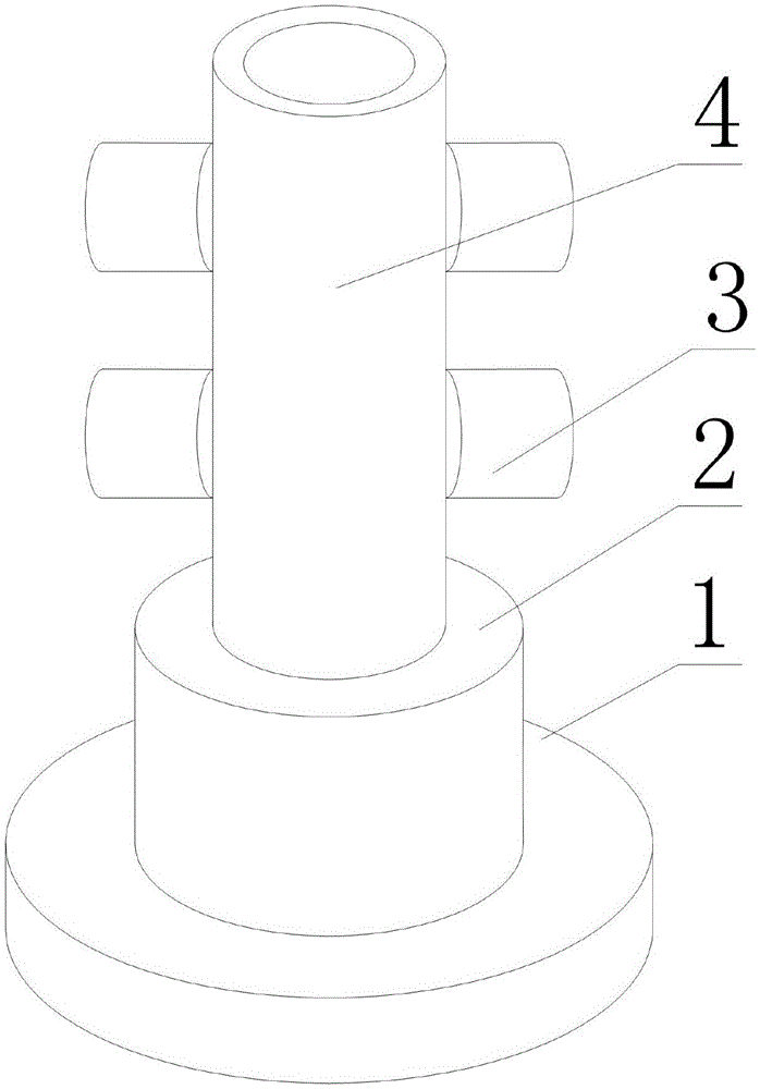
[0018] Such as figure 1 As shown, a method for analyzing the dynamic error of the spindle of a machine tool includes a shaft sleeve 4 and a sensor 3 arranged on the shaft sleeve 4. There are more than one sensor 3, and the sensors 3 are all fixed on the side of the shaft sleeve 4. On the wall, and the sensors 3 are all inductive sensors 3, the measurement points of each sensor 3 are not located on the same straight line.
[0019] In this embodiment, the provided shaft sleeve 4 is used to fix each sensor 3. When the shaft sleeve 4 is sleeved on the main shaft, each sensor 3 forms a plurality of non-contact sensors 3 relative to the main shaft to be measured, so that , this structure can be more conveniently installed on the main shaft of the lathe to complete the dynamic error and thermal deformation analysis of the main shaft; furthermore, the sensor 3 is further limited by the electric induction sensor 3, which can make the sensor 3 work in a wet environment It can still ens...
Embodiment 2
[0021] The present embodiment is further limited on the basis of embodiment 1, as figure 1 As shown, the further technical solution is: in order to facilitate the replacement of sensor 3 types or models according to specific measurement needs, the sensors 3 are provided with magnetic bases 1, and each sensor 3 is magnetically adhered to the sensor 3 by the magnetic base 1 on each On the shaft sleeve 4.
[0022] In order to make this structure have the function of braking the rotation of the main shaft, so as to enrich the scope of application of this structure, for example, it can be used for the test and analysis of a single main shaft that has been disengaged, and also includes a driving part 2 fixed at any end of the shaft sleeve 4 .
[0023] In order to facilitate the fixing of this structure, the base 1 is also fixed on the free end of the driving part 2 .
Embodiment 3
[0025] This embodiment is further limited on the basis of any one of the solutions provided by the above embodiments. In order to enable this structure to conveniently complete the measurement of the inclination and deflection of the main shaft, and the error analysis on the X-axis, Y-axis and Z-axis, the The number of sensors 3 is at least five.
PUM
 Abstract
Description
Claims
Application Information