Permanent magnet motor

A permanent magnet type, motor technology, applied in the direction of magnetic circuit, magnetic circuit rotating parts, magnetic circuit shape/style/structure, etc., can solve the problems of reduced driving torque, larger magnetic pole offset, and higher short-circuit magnetic flux ratio

Active Publication Date: 2018-07-31
AISIN SEIKI KK
View PDF9 Cites 1 Cited by
  • Summary
  • Abstract
  • Description
  • Claims
  • Application Information

AI Technical Summary

Problems solved by technology

However, when the magnets are embedded so that the radial direction is the long side direction, the amount of deviation of the magnetic poles due to the deflection increases, so the ratio of the magnetic flux in a short circuit increases, and the driving torque decreases significantly.
[0008] In this way, in the permanent magnet type motor with a skew structure, in order to suppress the reduction of the driving torque, there is still room for further improvement

Method used


Image

  • Permanent magnet motor
  • Permanent magnet motor
  • Permanent magnet motor

Examples


no. 1 approach

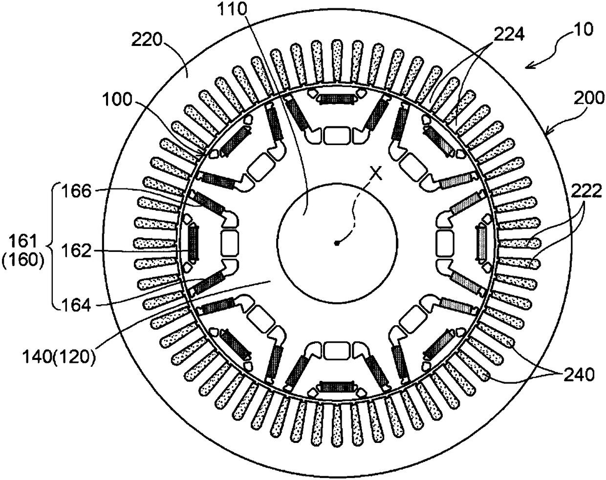
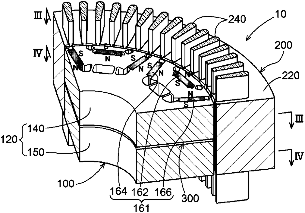
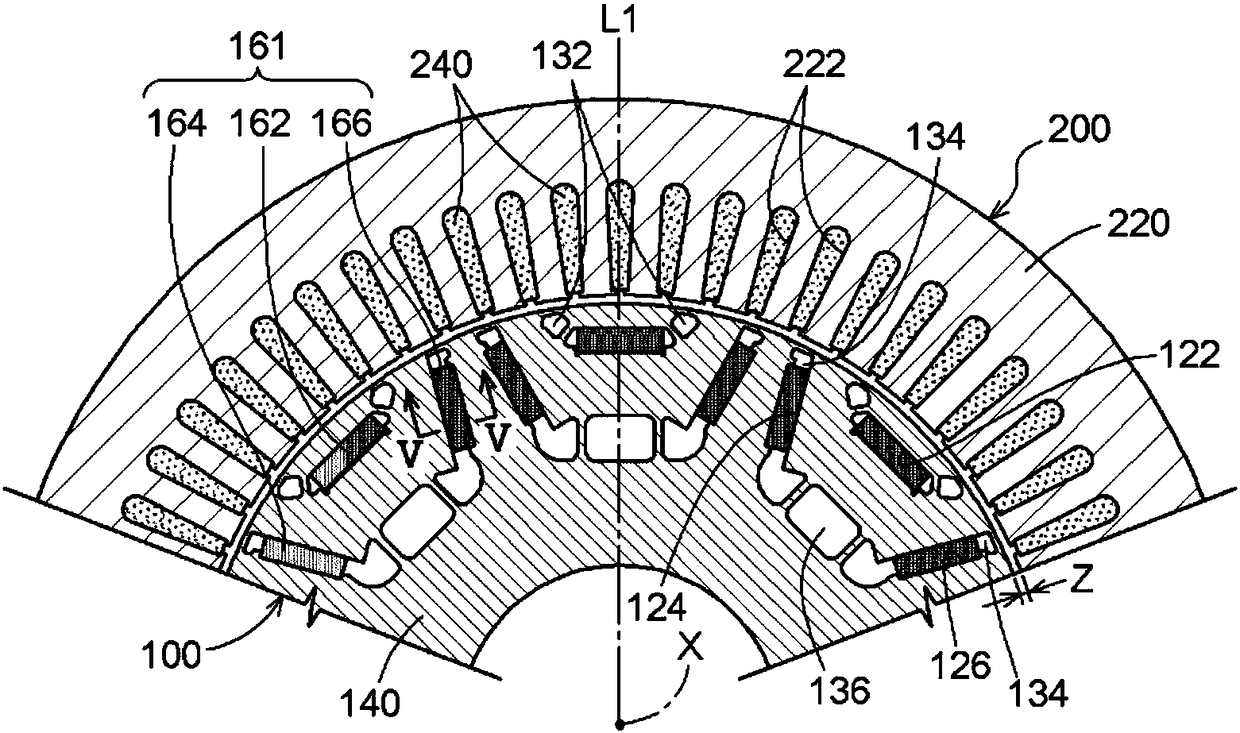
[0039] figure 1 It is a plan view of the embedded permanent magnet (IPM) motor 10 according to the first embodiment of the present invention viewed from the direction along the rotation axis. Such as figure 1 As shown, the IPM motor 10 has a rotor 100 and is coaxial with the axis X of the rotor 100 and has a gap Z on the radially outer side (refer to image 3 ) ground configuration of the stator 200. In addition, the IPM motor 10 is an example of a permanent magnet motor, and the gap Z is an example of the second gap.

[0040] The stator 200 has a stator core 220 and a coil 240 wound around a slot 222 of the stator core 220 . Stator core 220 is formed by laminating electromagnetic steel sheets and has a cylindrical shape.

[0041] The rotor 100 has a cylindrical rotor core 120 formed by laminating electromagnetic steel plates, a shaft 110 fixed through a through hole formed in the center of the rotor core 120 , and a cubic-shaped rotor core 120 accommodated inside the roto...

no. 2 approach

[0057] Hereinafter, an IPM motor 20 according to a second embodiment of the present invention will be described in detail with reference to the drawings. In the description of the present embodiment, the same reference numerals are attached to the positions of the same structures as those of the first embodiment, and the related description of the same structures will be omitted.

[0058] The IPM motor 20 is different from the first embodiment in that the first magnetic body 320 is inserted at the position of the gap 300 of the IPM motor 10 , and the other structures are the same as those of the first embodiment. The first magnetic body 320 is an example of a plate member, and the thickness of the first magnetic body 320 is an example of a first gap.

[0059] The first magnetic body 320 is formed by laminating one or more electromagnetic steel sheets constituting the rotor core 120 . The first magnetic body 320 is in contact with the lower surface of the upper iron core 140 a...

no. 3 approach

[0070] Hereinafter, an IPM motor 30 according to a third embodiment of the present invention will be described in detail with reference to the drawings. In the description of the present embodiment, the positions of the same configurations as those of the first embodiment and the second embodiment are assigned the same reference numerals, and related descriptions of the same configurations are omitted.

[0071] The IPM motor 30 is different from the second embodiment in that the second magnetic body 340 is inserted instead of the first magnetic body 320 that the IPM motor 20 has, and the other structures are the same as those of the second embodiment. The second magnetic body 340 is an example of a plate member, and the thickness of the second magnetic body 340 is an example of a first gap.

[0072] The second magnetic body 340 is formed by laminating one or more electromagnetic steel sheets. Such as Figure 10 As shown, compared with the first magnetic body 320, the charact...


PUM


Abstract

In order to minimize a reduction in drive torque in a permanent magnet motor having a skew structure, this permanent magnet motor is equipped with a rotor having: a rotor core formed by laminating multiple electromagnetic steel plates; and magnets housed in storage holes formed in the interior of the rotor core. The rotor core has a skew structure containing a first core and a second core, which are shifted with respect to each other in the circumferential direction with respect to the axis of the rotor. Among the magnets, first magnets are housed in the storage holes of the first core, and second magnets are housed in the storage holes of the second core. The first magnets and the second magnets oppose one another in the axial direction, with a first gap therebetween.

Description

technical field [0001] The present invention relates to permanent magnet type motors. Background technique [0002] It is known that in a motor using permanent magnets (for example, an IPM motor), torque fluctuations are generated when the motor is driven and rotated due to attractive and repulsive forces between magnets inserted into the rotor and slots of the stator. As one of the methods for reducing this torque fluctuation, it is proposed to adopt a skew structure (hereinafter also simply referred to as skew) for the rotor. [0003] Patent Document 1 discloses an invention in which a space for preventing short-circuiting of magnetic flux formed adjacent to a permanent magnet embedded in a rotor of a permanent magnet motor having a deflection extends inwardly from the inner edge of the end surface of the permanent magnet and Expand the width in the circumferential direction. By enlarging the width of the gap in the circumferential direction, when the rotor is divided in...

Claims


Application Information

Patent Timeline
Patent Type & Authority Applications(China)
IPC IPC(8): H02K1/27H02K16/02H02K21/16
CPCH02K16/02H02K2201/06H02K1/2766H02K21/16H02K1/27H02K29/03
Inventor 柴森贤子马晓鸥佐久间昌史
Owner AISIN SEIKI KK
Why Eureka
Try Eureka