Negative-pressure cup and needle combined device

A technology of negative pressure cans and negative pressure needles, applied in the field of negative pressure cans and needles, can solve the problems of blood pricking therapy being easily affected by human factors, poor treatment effect, high operation risk, etc., and achieves simple structure, small human errors, The effect of high treatment accuracy

Pending Publication Date: 2018-08-03
王永刚
View PDF5 Cites 5 Cited by
  • Summary
  • Abstract
  • Description
  • Claims
  • Application Information

AI Technical Summary

Problems solved by technology

[0004] The purpose of the present invention is to provide a negative pressure canned needle, which is used to solve the problems that the existing blood pricking therapy is easily affected by human factors, has high operational risk, complicated operation, large limitations, and poor therapeutic effect.

Method used


Image

  • Negative-pressure cup and needle combined device
  • Negative-pressure cup and needle combined device

Examples


Embodiment 1

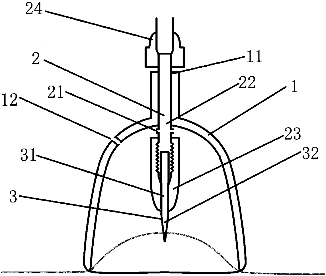
[0032] Such as figure 1 As shown, the negative pressure tank needle provided in this embodiment includes a coaxial tank body 1, a connecting piece 2 and a negative pressure needle 3. The tank body 1 is provided with an opening, and the closed end opposite to the opening position of the tank body 1 is provided. There are connecting holes 11 and extensions 12. Specifically, the extensions 12 extend toward the opposite direction of the opening of the tank 1 at the closed end of the tank body 1, and an extension hole (not shown) is arranged inside the extension 12 along its axial direction. ), and the extension hole is coaxial with the connection hole 11, and the top end of the connector 2 protrudes outside the extension portion 12 through the extension hole.

[0033] The connecting piece 2 is a hollow structure, the top of the connecting piece 2 extends out of the tank body 1, and the negative pressure needle 3 is detachably connected to the bottom end of the connecting piece 2. ...

Embodiment 2

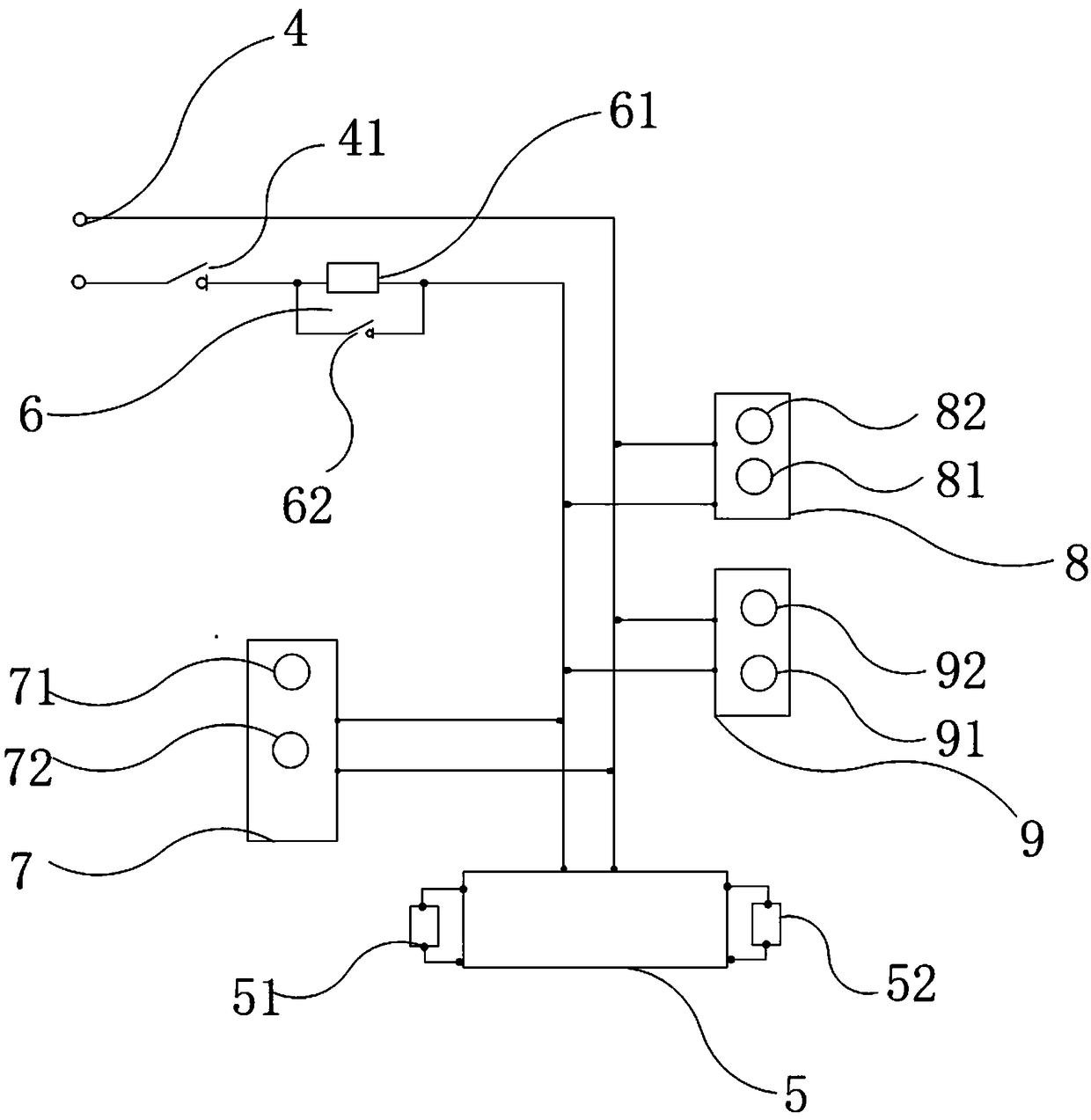
[0040] Such as figure 1 , figure 2 As shown, the negative pressure tank needle provided in this embodiment is used in connection with the negative pressure device. The structure of the negative pressure tank needle is the same as that of Embodiment 1. The negative pressure device includes: a housing (not shown), and a Power supply module 4, negative pressure generator 5 and line control switch 6.

[0041] The negative pressure generator 5 is connected in parallel with a pressure control module 51 and a negative pressure temperature control module 52, the input end of the negative pressure generator 5 is electrically connected with the power supply module 4, and the output end of the negative pressure generator 5 is connected with an exhaust pipe (not shown). , the exhaust pipe extends to the outside of the housing.

[0042] The line control switch 6 includes a touch screen automatic switch 61 and a manual switch 62, the touch screen automatic switch 61 is connected in series ...


PUM


Abstract

The invention discloses a negative-pressure cup and needle combined device, which comprises a cup body, a connecting piece and a negative-pressure needle which are coaxially arranged, wherein an opening is formed in the cup body; a connecting hole is formed in the closing end, opposite to the opening, of the cup body; the connecting piece is inserted into the connecting hole, and the bottom end ofthe connecting piece extends into the cup body; the top end of the connecting piece extends out of the cup body; the negative-pressure needle is detachably connected to the bottom end of the connecting piece; the connecting piece is of a hollow structure; an airflow through hole is formed in the part, which is located within the cup body, of the sidewall of the connecting piece, and via the airflow through hole, airflow inside the cup body communicates with airflow outside the cup body; and a pneumatic valve hole, which runs through the thickness of the cup body, is formed in the sidewall ofthe cup body. The negative-pressure cup and needle combined device, which can be operated by a single hand, is convenient to use, high in accuracy rate and broad in application scope; the negative-pressure needle can be flexibly detached so as to facilitate replacing, and the negative-pressure needle is convenient and sanitary and is high in safety; and moreover, the negative-pressure cup and needle combined device is simple in structure and low in production cost.

Description

technical field [0001] The invention relates to the technical field of medical equipment, in particular to a negative pressure tank needle. Background technique [0002] In the medical field, acupuncture and cupping therapy has a long history and is widely used. Acupuncture and cupping therapy can not only maintain health, but also treat rheumatic arthralgia, intractable rheumatic pain, old muscle and bone injuries, sciatica, lumbar disc herniation and other diseases. [0003] The operation method of the traditional blood pricking therapy is as follows: first perform acupuncture on the designated part, and after a certain amount of stimulation is reached, then take the blood pricking as the center and pull out the cupping, so as to increase the therapeutic effect. This operation method has extremely high requirements on the operator. The operator needs to determine the depth of acupuncture and the retention time based on experience, so as to be light, shallow, fast and accu...

Claims


Application Information

Patent Timeline
Patent Type & Authority Applications(China)
IPC IPC(8): A61H9/00A61H39/08A61M1/08
CPCA61M1/08A61H9/0057A61H39/086
Inventor 王永刚
Owner 王永刚
Why Eureka
Try Eureka