LED lamp filament column welding equipment

A technology of LED filament and welding equipment, applied in welding equipment, resistance welding equipment, metal processing equipment, etc., can solve the problems of long time, increased workload, fracture damage, etc.

Pending Publication Date: 2018-08-03
GUANGZHOU MINGSEN TECH CO LTD
View PDF8 Cites 3 Cited by
  • Summary
  • Abstract
  • Description
  • Claims
  • Application Information

AI Technical Summary

Problems solved by technology

[0005] 1. Due to the small size and cylindrical shape of the LED filament column, it is difficult to clamp and fix it, and the middle part of the filament column is made of fluorescent glue (like a candle), and a slightly larger clamping force will cause It is broken and damaged, so when it is fixed, it will often be broken and damaged, and the broken damage is not easy to be found, and it will still be welded to the glass column, which will lead to an increase in the scrap rate and affect the quality of the product on the one hand. , on the other hand, it is necessary to rework the scrap, which increases the workload
[0006] 2. Since it is difficult to control the amount of solder and welding temperature during manual welding, there will be poor contact, which makes it difficult to guarantee the quality of the product
[0007] 3. Each step of the above-mentioned welding requires the operator to be careful and careful, so the requirements for the operator are high, and the entire welding operation has many processes and takes a long time, resulting in a long welding cycle, resulting in low welding efficiency and low output

Method used


Image

  • LED lamp filament column welding equipment
  • LED lamp filament column welding equipment
  • LED lamp filament column welding equipment

Examples


Embodiment Construction

[0059] The present invention will be further described in detail below in conjunction with the embodiments and the accompanying drawings, but the embodiments of the present invention are not limited thereto.

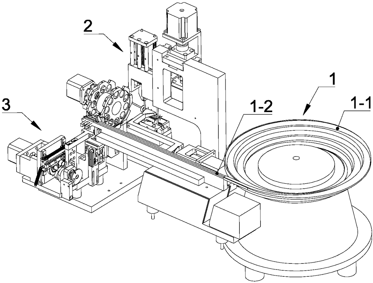
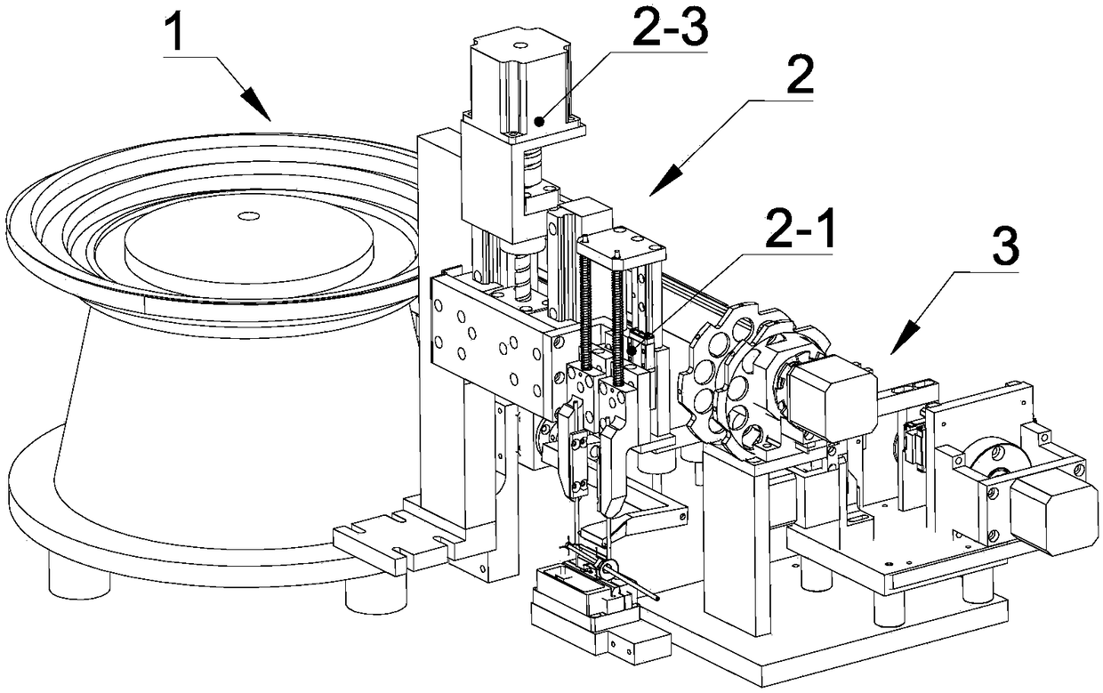
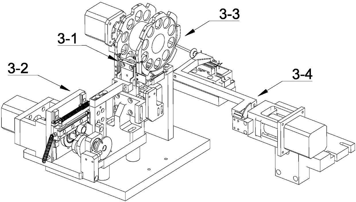
[0060] see figure 1 , figure 2 , image 3 and Figure 17 , a kind of LED filament post welding equipment of the present invention comprises a feeding module 1, a welding module 2 and a material handling module 3 for transferring the LED filament post 6 from the feeding module 1 to the welding module 2; the feeding module 1 It includes a vibrating plate 1-1 and a vibrating guide rail 1-2 connected to the discharge port of the vibrating plate 1-1; the welding module 2 is provided with a welding execution device, which includes a spot welder 2-1, located at a point The two electrode columns 2-2 below the two welding pins 2-11 of the welding machine 2-1 and the spot welding machine lifting drive mechanism 2-3 that drives the spot welding pins 2-11 to move up and down; th...


PUM


Abstract

The invention discloses LED lamp filament column welding equipment. The LED lamp filament column welding equipment comprises a feeding module, a welding module and a material carrying module used fortransferring LED lamp filament columns to the welding module from the feeding module. The feeding module comprises a vibration disc and a vibration guide rail connected with a discharging port of thevibration disc. The welding module is provided with a welding executing device. The welding executing device comprises a pot welding machine, two electrode columns and a spot welding machine lifting driving mechanism for driving a spot welding needle to move up and down. The material carrying module comprises a supporting positioning mechanism, a first material carrying device for carrying the LEDlamp filament columns to the supporting positioning mechanism from the vibration guide rail, a material taking carrying device for carrying the LED lamp filament columns away from the supporting positioning mechanism, and a discharging carrying device used for carrying the LED lamp filament columns to the two electrode columns from the material taking carrying device. According to the equipment,LED lamp filament column carrying and positioning work and welding work in the welding process can be automatically finished, and the beneficial effects that the welding effect is good, and the welding efficiency is high are achieved.

Description

technical field [0001] The invention relates to a welding device, in particular to an LED filament column welding device. Background technique [0002] LED filament as a decorative lighting has been more and more loved by people. Different from ordinary incandescent lamps, the glass column inside the LED filament is welded on the LED filament column. The filament column has strong illuminance, luminous The advantages of large area and high color rendering index can bring people a new vision of light. Wherein, in the manufacturing process of the LED filament, it is necessary to weld the LED filament column to the glass column. [0003] Due to the small size of the LED filament column, it is not easy to clamp and carry. The welding tasks of the existing LED filament column are all completed manually. Specifically, the manual welding needs to complete the following tasks in sequence: (1) Welding of the LED filament column (2) Fit a pair of welding wires of the glass column an...

Claims


Application Information

Patent Timeline
Patent Type & Authority Applications(China)
IPC IPC(8): B23K11/11B23K11/36
CPCB23K11/11B23K11/36
Inventor 王姝刘宇冷纯镁王超夏宇嫦刘秋雄
Owner GUANGZHOU MINGSEN TECH CO LTD
Why Eureka
Try Eureka