Yarn knotting method

A technology of yarn and yarn frame, which is applied in the direction of conveying filamentous materials, thin material processing, transportation and packaging, etc. It can solve the problems of large knots, unfavorable industrialized actual production, and inability to disperse automatically, so as to meet the requirements of continuous production needs

Inactive Publication Date: 2018-08-03
JUSHI GRP CO
View PDF10 Cites 2 Cited by
  • Summary
  • Abstract
  • Description
  • Claims
  • Application Information

AI Technical Summary

Problems solved by technology

In the process of use, after the previous yarn roll is used up, it needs to be shut down to connect the next yarn roll to continue production, which greatly affects the use efficiency of glass fiber yarn and cannot meet the needs of automated high-efficiency production.
Connecting two yarn clusters end to end can meet the needs of continuous production. However, due to the characteristics of glass fiber yarns, knotting in ordinary methods will cause large knots and cannot be automatically dispersed, which is not conducive to industrial production.
[0003] In view of this, three sets of multi-locking knots and knotting methods are disclosed in the patent literature with the publication number CN105179596A. The scheme of the invention is: first tie a single knot, and in the untensioned single knot, put the sleeve rod along one The direction of the side rope is penetrated into it, let the other side rope follow the original direction to encircle the sleeve rod, and go around the sleeve rod 360°, judge and memorize its rotation direction, or reverse the side rope along the sleeve rod 360° ; Then pull out the back-facing rope along the sleeve rod to form a rope ring, turn the pulled rope ring 180° according to the memorized direction of rotation, then turn 90°~180° back and hang it on the sleeve rod , the knotting method disclosed in the above reference document has the disadvantages of large knots and cannot be automatically dispersed

Method used


Image

  • Yarn knotting method
  • Yarn knotting method
  • Yarn knotting method

Examples


Embodiment Construction

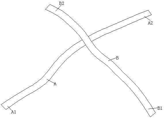
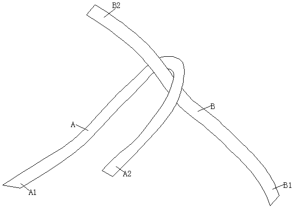
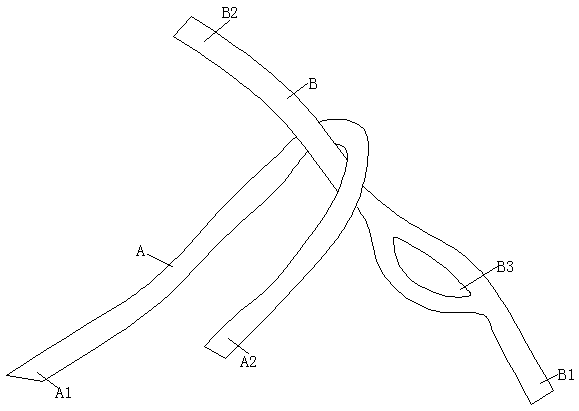
[0030] The present invention will be further described in detail below in conjunction with the accompanying drawings and examples. The following examples are explanations of the present invention and the present invention is not limited to the following examples.

[0031] see Figure 1 to Figure 6 It should be noted that the structures, proportions, sizes, etc. shown in the drawings attached to this specification are only used to match the content disclosed in the specification, for those who are familiar with this technology to understand and read, and are not used to limit the present invention Therefore, it has no technical substantive meaning, and any modification of structure, change of proportional relationship or adjustment of size shall still fall into the within the scope covered by the technical content disclosed in the present invention. At the same time, if terms such as "upper", "lower", "left", "right", "middle" and "one" are used in this specification, they are...


PUM


Abstract

The invention relates to a yarn knotting method. The yarn knotting method is applicable to yarn connection, and comprises the following steps: a length of No.1 yarn is measured starting from the tailend of the No.1 yarn; the No.1 yarn is erected on the upper side of No.2 yarn; a first knot position is set on the No.1 yarn; the head end of the No.2 yarn is rotated around the No.1 yarn as the central axis; the head end of the No.1 yarn is allowed to penetrate through an opening; the head end of the No.1 yarn is allowed to be in flush with that of the No.2 yarn, and a first knot is determined atthe moment; the tail end of the No.2 yarn is positioned on the lower side of the No.2 yarn, and a pull ring is formed through rotation; the combined tail ends of the No.1 yarn and the No.2 yarn are allowed to upward penetrate through the lower side of the pull ring and then are tensioned, and a second knot is determined at the moment; and the first knot and the second knot are placed in an innerring of the tail end of the No.2 yarn. By adoption of the yarn knotting method provided by the invention, the head-to-tail connection between yarn coils can be achieved, thereby meeting the continuousproduction demand; and furthermore, the connected knots can be automatically untied, thereby avoiding the influence on the product usability and the finished product quality.

Description

technical field [0001] The invention relates to a yarn knotting method, which is suitable for the connection between yarns, especially for the connection between glass fiber plied untwisted roving clusters. Background technique [0002] At present, the glass fiber plied rovings packaged in pallets are packaged independently and without connection between each yarn cluster. During use, after the previous yarn roll is used up, it needs to be shut down to connect the next yarn roll to continue production, which greatly affects the use efficiency of glass fiber yarn and cannot meet the needs of automated high-efficiency production. Connecting two yarn clusters end-to-end can meet the needs of continuous production, but due to the characteristics of glass fiber yarns, knotting in ordinary methods will cause large knots and cannot be automatically dispersed, which is not conducive to industrial actual production. [0003] In view of this, three sets of multi-locking knots and kno...

Claims


Application Information

Patent Timeline
Patent Type & Authority Applications(China)
IPC IPC(8): B65H69/04
CPCB65H69/04
Inventor 费建春马明锋
Owner JUSHI GRP CO
Why Eureka
Try Eureka