Electroplating die of connector terminal

A connector terminal and mold technology, applied in the electrolysis process, electrolysis components and other directions, can solve the problems of wear of metal terminals and the feeding port of electroplating equipment, large demand for precious metal plating solution, large consumption of precious metal, etc., and achieves high practicability. , Wide range of application, the effect of saving occupancy

Pending Publication Date: 2018-08-03
SUZHOU PLATER ELECTRONICS CO LTD
View PDF4 Cites 0 Cited by
  • Summary
  • Abstract
  • Description
  • Claims
  • Application Information

AI Technical Summary

Problems solved by technology

[0003] At present, the existing electroplating mold usually clamps and places the metal terminal into the solution tank for electroplating, which requires a large amount of precious metal electroplating solution and is troublesome to store. In addition, when the existing electroplating equipment sends the metal terminal to the next process, it is easy to be unstable during transportation, causing the metal terminal to contact with the feed port of the electroplating equipment and thus being worn out, affecting product quality

Method used


Image

  • Electroplating die of connector terminal
  • Electroplating die of connector terminal
  • Electroplating die of connector terminal

Examples


Embodiment Construction

[0019] The following will clearly and completely describe the technical solutions in the embodiments of the present invention with reference to the accompanying drawings in the embodiments of the present invention. Obviously, the described embodiments are only some, not all, embodiments of the present invention. Based on the embodiments of the present invention, all other embodiments obtained by persons of ordinary skill in the art without making creative efforts belong to the protection scope of the present invention.

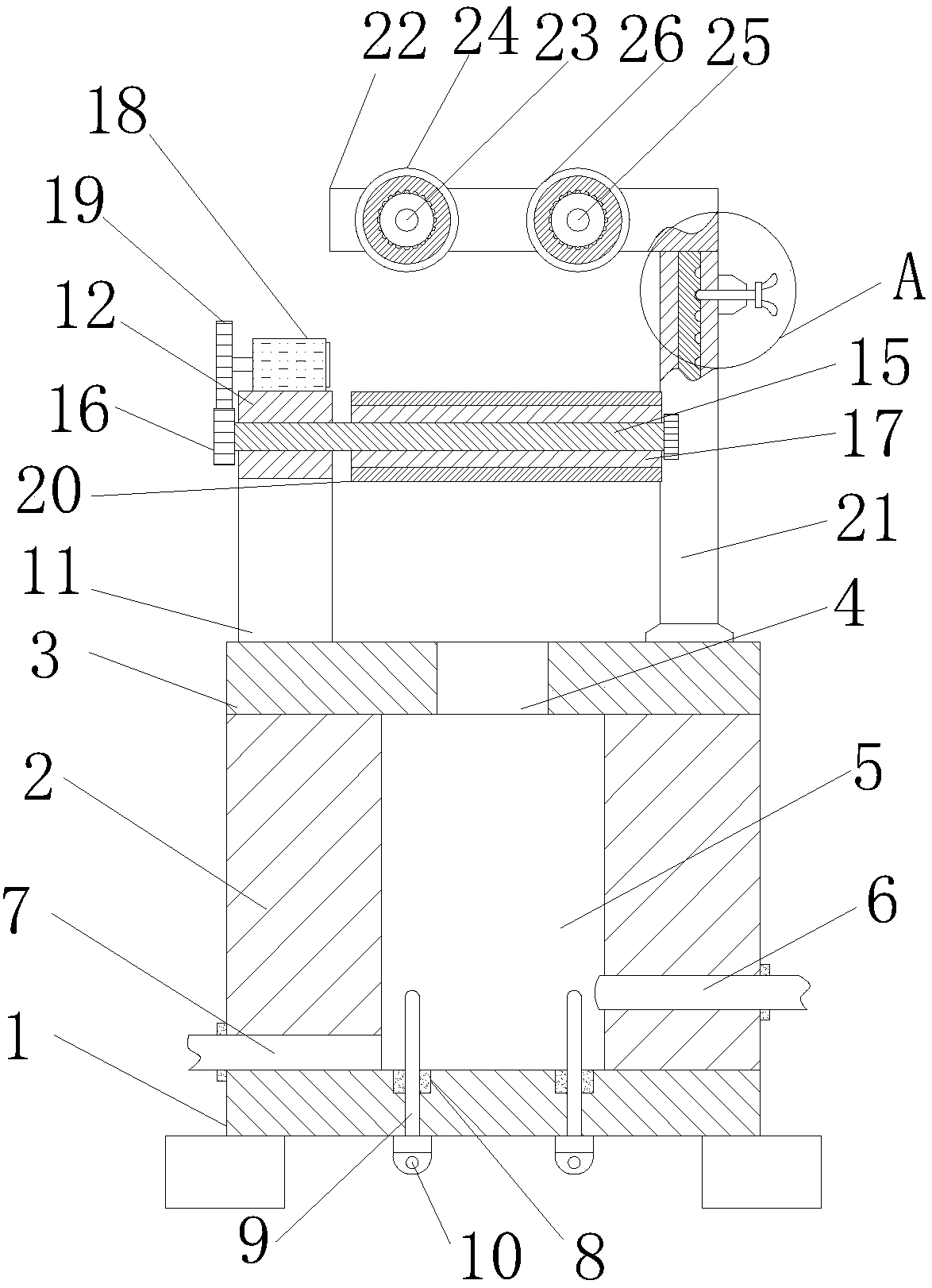
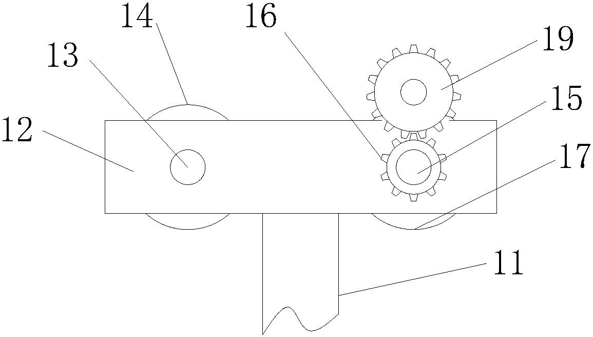
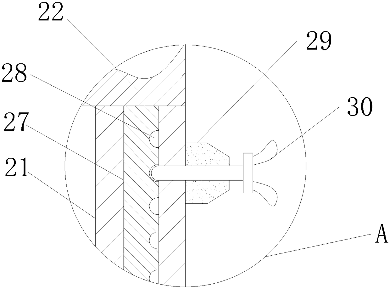
[0020] see Figure 1~3 , in an embodiment of the present invention, a connector terminal electroplating mold includes a base plate 1, a cover plate 3 and a second cross arm 22, the upper end of the base plate 1 is provided with a slotted plate 2, and the upper end of the slotted plate 2 is provided with a Cover plate 3, a circular through hole 4 is arranged in the upper middle part of the cover plate 3, a hole groove 5 is arranged in the upper middle part of t...


PUM


Abstract

The invention discloses an electroplating die of a connector terminal. The electroplating die comprises a bottom plate, a cover plate and a second cross arm, wherein hole groove plates are arranged atthe upper end of the bottom plate, and the cover plate is arranged at the upper end of the hole groove plates. The electroplating die is reasonable in structure and high in practicability; during work, a first conduction wheel and a second conduction wheel can effectively prevent the connector terminal from moving forwards and backwards during feeding, and a third conduction wheel and a fourth conduction wheel can effectively prevent the connector terminal from moving leftwards and rightwards during feeding, so that the feeding of the connecting terminal is stable and accurate, the workload of debugging of workers is greatly reduced, and the production efficiency is improved; positioning nuts and positioning holes can adjust the height of a second cross arm, so that the application rangeis wider; and a motor drives the connector terminal to stably enter a hole groove at a constant speed through the second conduction wheel, and the situation that the electroplating quality is influenced by collision during manual operation is avoided. The electroplating die is small and exquisite in use, saves the occupied amount of the electroplating solution, improves the quality of the coating,and reduces the consumption of noble metals.

Description

technical field [0001] The invention relates to the field of electroplating molds, in particular to a connector terminal electroplating mold. Background technique [0002] Electroplating technology has been widely used in products connected with metal terminals, such as pins, pressing pieces, screws and other parts, which need to be electroplated to meet their specific functions and lifespan. Electroplating is to use electrolysis under the action of direct current. The process of depositing metal or alloy on the surface of a metal workpiece to form a uniform, dense, and well-bonded metal surface. Existing electrical connector terminals use high-performance copper alloy as the base material to provide the elasticity required for mechanical properties. In order to prevent the base material from corroding in the application environment, a nickel plating layer is plated on the base material surface, and then the terminal contact part and installation The part is then plated wit...

Claims


Application Information

Patent Timeline
Patent Type & Authority Applications(China)
IPC IPC(8): C25D17/08C25D17/16C25D7/00
CPCC25D7/00C25D17/08C25D17/16
Inventor 邓金虎
Owner SUZHOU PLATER ELECTRONICS CO LTD
Why Eureka
Try Eureka