Water cutoff structure of covered wire

A covered wire and water-stop technology, which is applied in the direction of cable joints, bases/shells, and connection insulation, can solve the problems of poor water-stop function, prolong welding time, increase costs, etc., achieve high water-stop function, and eliminate welding dispersion Effect

Inactive Publication Date: 2006-10-18
YAZAKI CORP
View PDF3 Cites 0 Cited by
  • Summary
  • Abstract
  • Description
  • Claims
  • Application Information

AI Technical Summary

Problems solved by technology

[0009] According to the structure of the above-mentioned water-stop part, there is no structure to concentrate the ultrasonic welding energy to the part to be welded, so the welding time is prolonged and the cost is increased
[0010] Moreover, as shown in Figures 14 and 15, due to the unsealed structure, there is also the problem of poor water-stop function
[0011] Furthermore, the melted cover of the electric wire protrudes to the outside and damages the cover of the electric wire other than the welded portion, and there arises a problem that stable adhesion and stable insulating performance of the electric wire cannot be ensured.

Method used


Image

  • Water cutoff structure of covered wire
  • Water cutoff structure of covered wire
  • Water cutoff structure of covered wire

Examples


Embodiment Construction

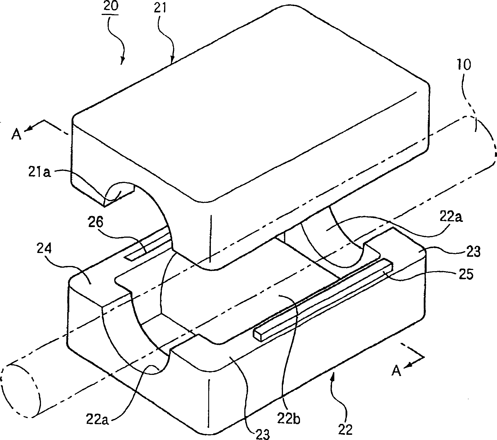
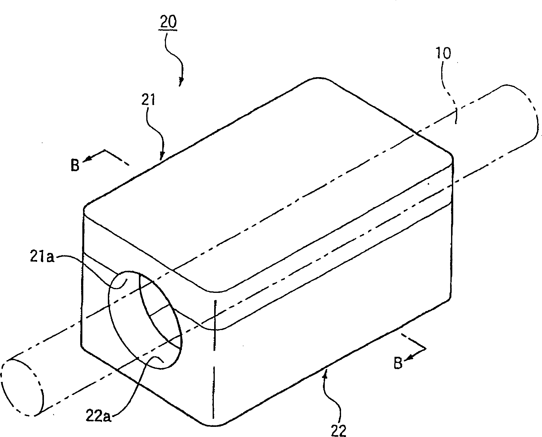
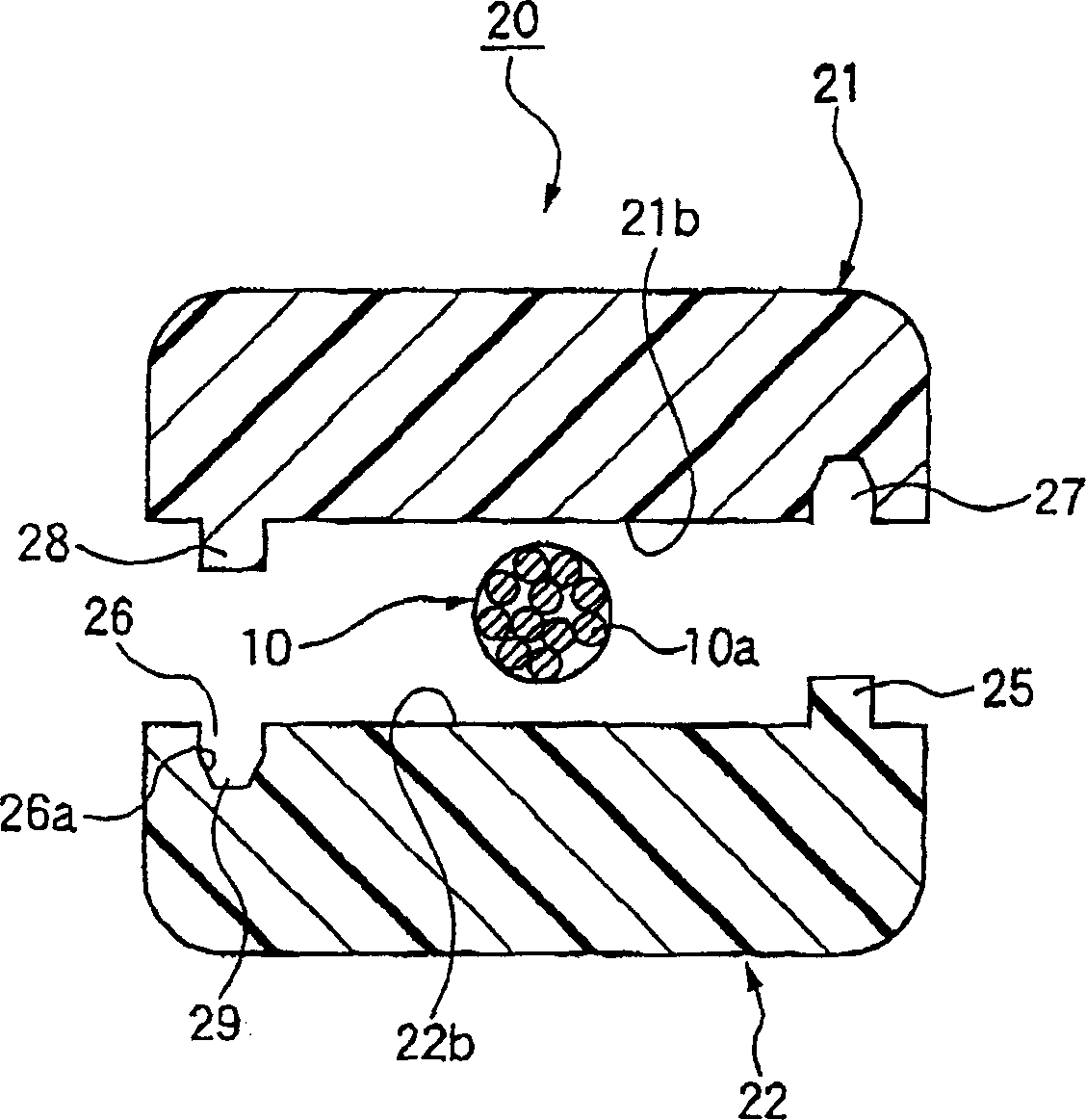
[0083] See below Figure 1 to Figure 5 A first embodiment of the waterproof structure of the covered wire according to the present invention will be described. figure 1 is an exploded perspective view of the waterproof structure of the covered wire according to the embodiment of the present invention. figure 2 is displayed figure 1 Perspective view of the waterstop structure shown after it has been ultrasonically welded. Figure 3A with 3B yes figure 1 Sectional view of the waterstop structure shown. Figure 3A It is an edge showing the state before clamping the covered wire figure 1 3B is a cross-sectional view showing the state of ultrasonic welding of the covered wire figure 2 Cutaway view of B-B. and, Figure 4A is the display assembly figure 1 Sectional view before locking part of the shown waterstop. Figure 4B It is a sectional view after showing the locking part where the water stop structure is fitted. Figure 5 is a perspective view of a water stop ...


PUM


Abstract

A water cutoff structure of a covered wire according to the invention is characterized in a water cutoff structure of a covered wire comprising an upper side member and a lower side member for carrying out water cutoff to the covered wire by sandwiching a covered wire constituted by covering core lines by a pair of water cutoff members made of a resin respectively provided at the upper side member and the lower side member to be subjected to ultrasonic welding, in which the lower side member of the water cutoff structure is provided with a pair of locking portions and the pair of locking portions are respectively fitted to a pair of locking portions provided to correspond to the upper side member. According to the structure, ultrasonic vibration energy is transmitted to concentrate on a welded portion. Therefore, ultrasonic wave energy is efficiently transmitted and time period dissipated in welding is shortened.

Description

[0001] This application is a divisional application of an invention patent application titled "Waterstop Structure of Covered Wire", application number 200310104571.1, and application date October 18, 2003. technical field [0002] The present invention relates to a waterproof structure of a covered wire used in electric wiring systems such as automobiles, and more particularly to a structure in which a covered wire made of a covered core wire is sandwiched between a water-stopping element made of resin and ultrasonically welded to seal the water of the covered wire . Background technique [0003] In the automotive electrical wiring system, water can continuously intrude between the core wires of the covered wire through the gap, so the water can reach the inside of the control unit and other equipment. In order to prevent water intrusion, the electrical wiring system used in the part where water intrusion is usually provided with a water-stop structure. [0004] As an exam...

Claims


Application Information

Patent Timeline
Patent Type & Authority Applications(China)
IPC IPC(8): H01R4/70H01R13/52H02G15/08
Inventor 朝仓信幸井出哲郎
Owner YAZAKI CORP
Why Eureka
Try Eureka