Bubbling brick

a brick and brick technology, applied in the field of bricks, can solve the problem of introducing a relatively large amount of energy into the reaction of oxyhydrogen gas

Inactive Publication Date: 2009-02-19
LINDE AG
View PDF6 Cites 6 Cited by
  • Summary
  • Abstract
  • Description
  • Claims
  • Application Information

AI Technical Summary

Benefits of technology

[0003]In addition to chemical refining processes, it is possible to purge the melt of gas components by purposefully introducing gas bubbles into the melt (bubbling), namely by injecting an external gas, and thusly causing a mass transfer. Due to the size of the bubbles, a forced convection is primarily realized in the melt. The driving force for the mass transfer from the melt into the bubble is the concentration difference between the concentration of the gases dissolved in the melt and the concentration of the gases in the bubble. The diffusion of gaseous components into the melt is associated with a growth of the bubble that increases the rate of ascent. A very effective mass transfer between the melt and the bubble is achieved due to a large specific surface (very large quantity of small bubbles).
[0006]In certain instances, bubbling can also be carried out with pure oxygen rather than air, wherein this not only makes it possible to influence the glass flow in the above-described fashion, but also to prevent any influence of air components other than oxygen.
[0012]In one embodiment of the invention, one or two displaceable nozzle tubes that preferably consist of a heat-resistant ceramic material are provided within the bores. This (these) tube(s) can be displaced inward and outward such that the height of the reaction point can be shifted. This makes it possible to optimally adapt the reaction to the requirements of the glass melt. The so-called bubbling brick therefore contains at least two bores that the inclined relative to one another at an acute angle such that their alignments intersect within the glass melt when the bubbling brick is inserted into the bottom of the glass melt trough.

Problems solved by technology

It has also been attempted to carry out bubbling with water vapor, but these attempts were unsuccessful because this water vapor withdraws energy from the glass melt and therefore advantageously affects the glass quality.
If hydrogen is introduced as the flammable gas, the resulting oxyhydrogen gas reaction introduces a relatively large amount of energy.

Method used


Image

  • Bubbling brick
  • Bubbling brick
  • Bubbling brick

Examples


Embodiment Construction

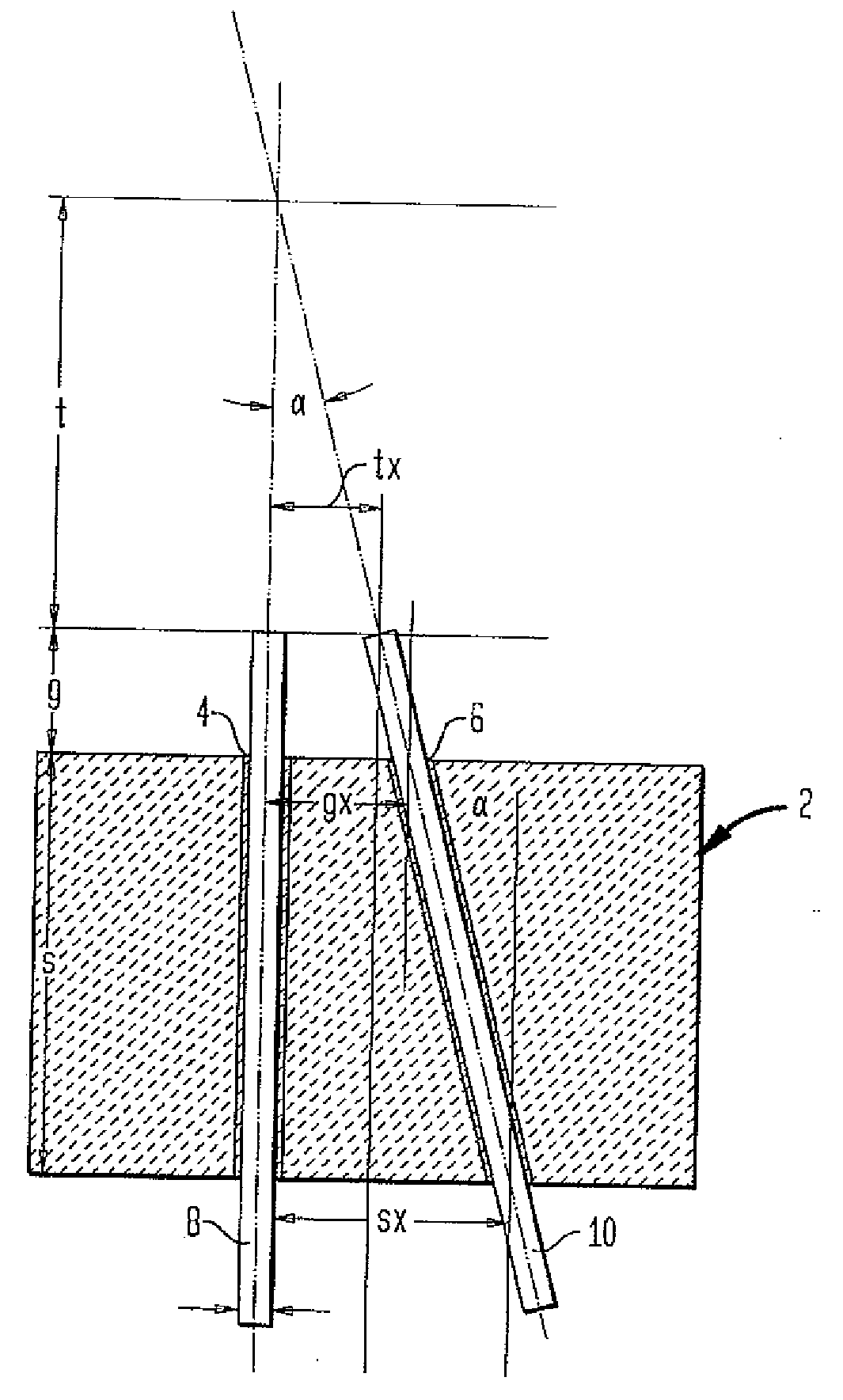
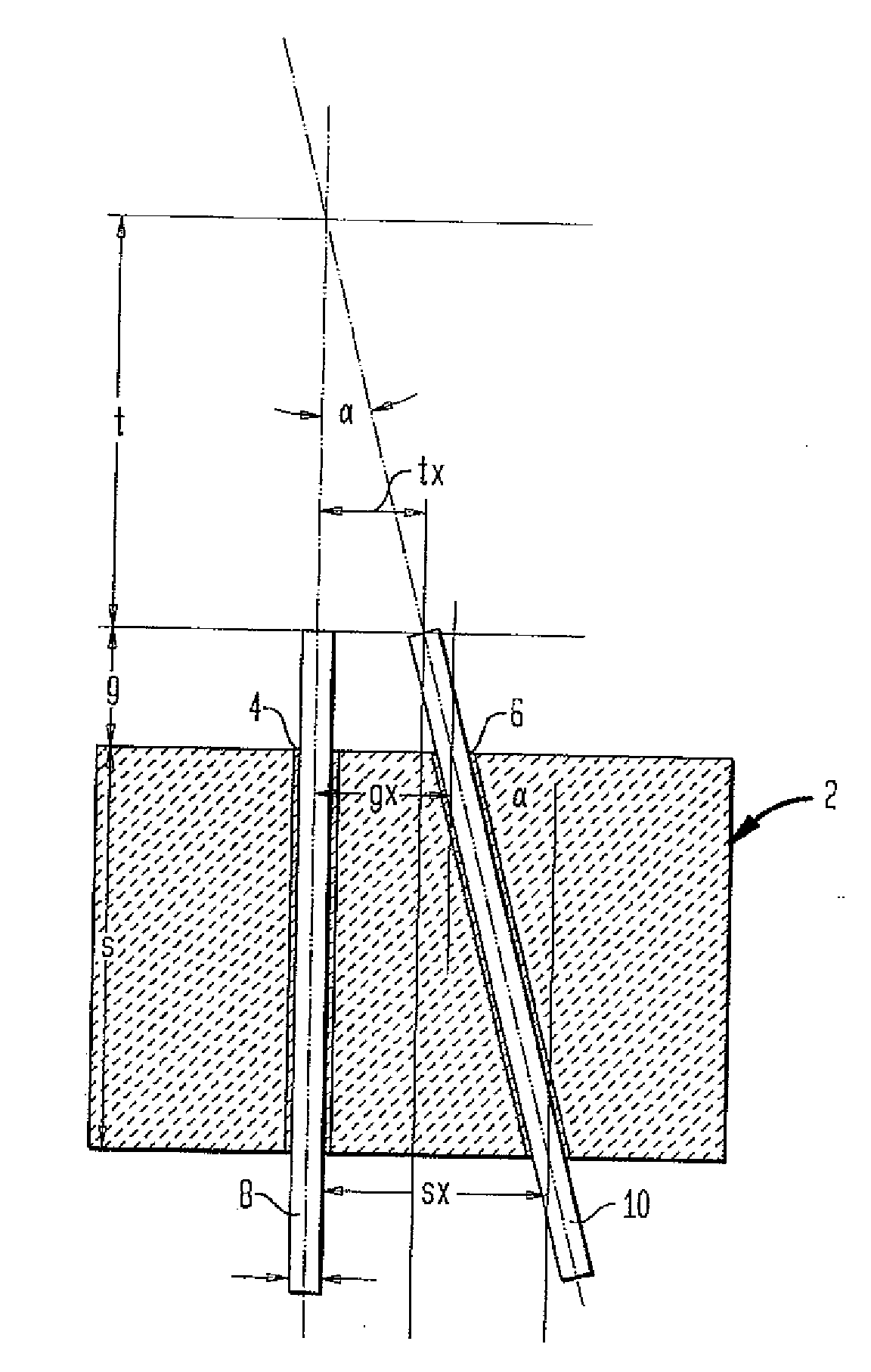
[0014]The FIGURE shows the bubbling brick 2 with the two bores 4 and 6, wherein the bore 4 is realized vertically and the bore 6 is inclined by an angle α. The nozzle tubes 8 and 10 arranged within the bores 4 and 6 have a length that is greater than the thickness of the bubbling brick 2 and can be displaced upward and downward such that their tips can be adjusted to a certain height g within the glass melt. Due to these measures, the spacing of the gas outlets tx can be adapted to the glass melt conditions.

[0015]The following equations applied to the variables t, gx and α:

t=-g·tx-s·txtx-sxgx=tx+g·txtα=arctan(sxt+g+s)

[0016]One preferred spacing between the nozzles 8,10 lies between 30 and 60 mm. However, it would also be possible to use spacings between 20 and 100 mm. The diameter of the bores 4 or 6 preferably amounts to 15 mm. A few preferred dimensions are indicated in the following table:

Minimum nozzle spacingtxmm30Maximum spacing from brick surfacegmm150Spacing between outlets ...


PUM

PropertyMeasurementUnit
angleaaaaaaaaaa
angleaaaaaaaaaa
angleaaaaaaaaaa

Abstract

The invention pertains to a bubbling brick with at least two bores for introducing two different gases into a glass melt. In order to increase the variability of the glass melt process, these bores together form an included angle α>0.

Description

[0001]The invention pertains to a bubbling brick for introducing two different gases into a glass melt.[0002]This bubbling brick is primarily used in refining inorganic compounds in molten form, particularly glass melts. In the manufacture of glass, it is necessary to carry out a refining process after the melting process. The refining serves for removing physically and chemically bound gases from the molten glass. The gases need to be removed so as to not impair the quality of the end product.[0003]In addition to chemical refining processes, it is possible to purge the melt of gas components by purposefully introducing gas bubbles into the melt (bubbling), namely by injecting an external gas, and thusly causing a mass transfer. Due to the size of the bubbles, a forced convection is primarily realized in the melt. The driving force for the mass transfer from the melt into the bubble is the concentration difference between the concentration of the gases dissolved in the melt and the ...

Claims


Application Information

Patent Timeline
Patent Type & Authority Applications(United States)
IPC IPC(8): C03B5/16
CPCC03B5/193C03B5/2356F27D3/16F23M5/025F27D2003/164C03B5/42F27D27/00
Inventor GORISCH, MATTHIASMAHRENHOLTZ, HANS
Owner LINDE AG
Why Eureka
Try Eureka