
System and method for oxygenating an aerobic sludge digester

a technology of aerobic sludge digester and oxygenation system, which is applied in the direction of multi-stage water/sewage treatment, filtration separation, separation process, etc., can solve the problems of high operating cost of conventional air-based aerobic sludge digester, and achieve the effect of increasing the bubble residence time and mass transfer efficiency

Inactive Publication Date: 2008-05-22
PRAXAIR TECH INC
View PDF27 Cites 5 Cited by
  • Summary
  • Abstract
  • Description
  • Claims
  • Application Information

AI Technical Summary

Benefits of technology

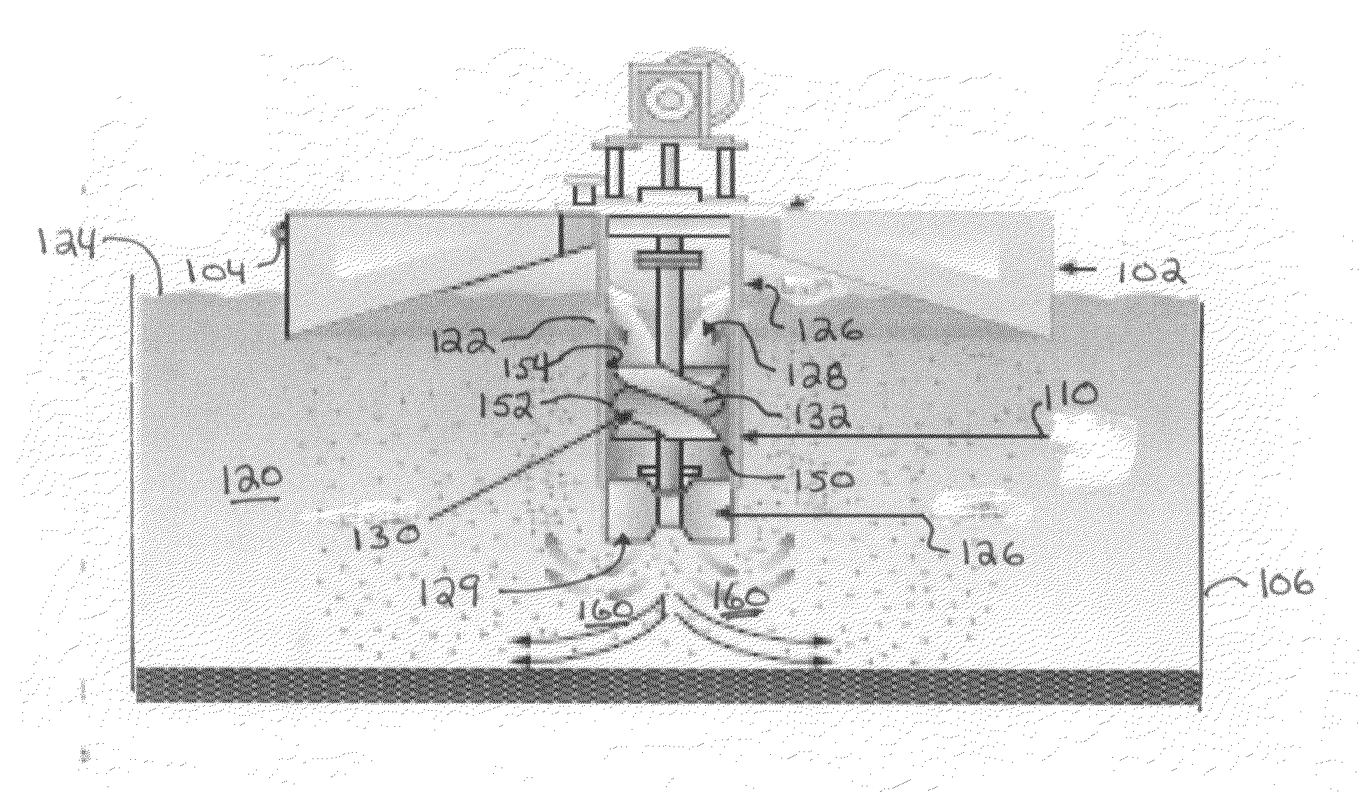
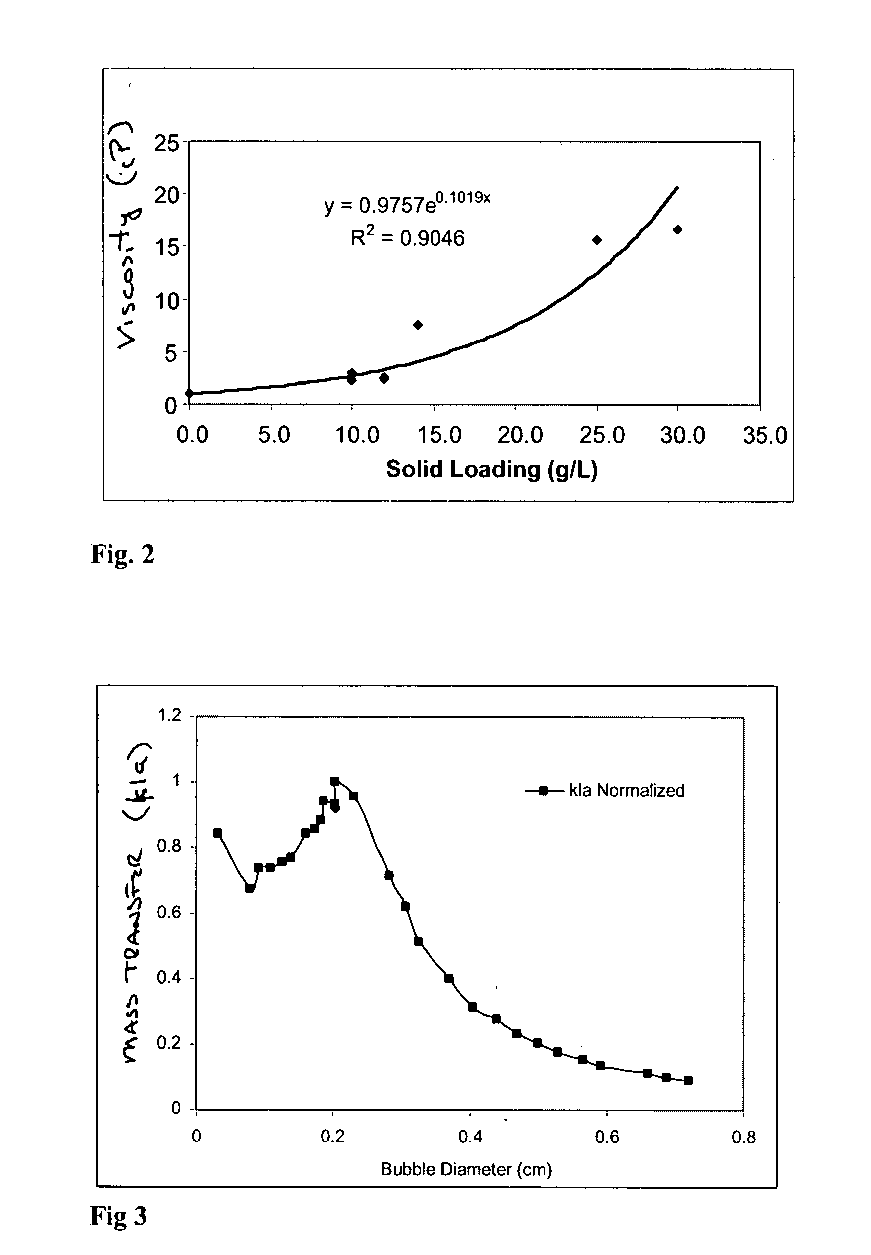
[0008]In one aspect, the present invention may be characterized as a method of treating high-solids content material in an aerobic digester of a wastewater system, the aerobic digester having a mechanically agitated contactor disposed therein, the method comprising the steps of (a) disposing the high-solids content material within the aerobic digester; (b) introducing oxygen into the aerobic digester at a location proximate to the mechanically agitated contactor; (c) agitating the high-solids content material and oxygen to produce gas bubbles within the high-solids content material, the gas bubbles having an average diameter of between about 0.3 mm and 3.0 mm; and (d) dispersing the high-solids content material including the gas bubbles into the aerobic digester to increase residency time of the gas bubbles within the aerobic digester.
[0010]The mass transfer efficiency associated with the present methods and system are enhanced as a result of the combined effect of the bubble size, the oxygen dissolution into the sludge at a location near the hydrodynamic structure and greater bubble residence time of the oxygen bubbles within the sludge in the aerobic digester.

Problems solved by technology

Unfortunately, conventional air-based aerobic sludge digestion systems tend to have higher operating costs mainly attributable to the consumption of excessive amounts of power, on average about 1500 hp per million gallons of treated material.

Method used


Image

  • System and method for oxygenating an aerobic sludge digester
  • System and method for oxygenating an aerobic sludge digester
  • System and method for oxygenating an aerobic sludge digester

Examples


Embodiment Construction

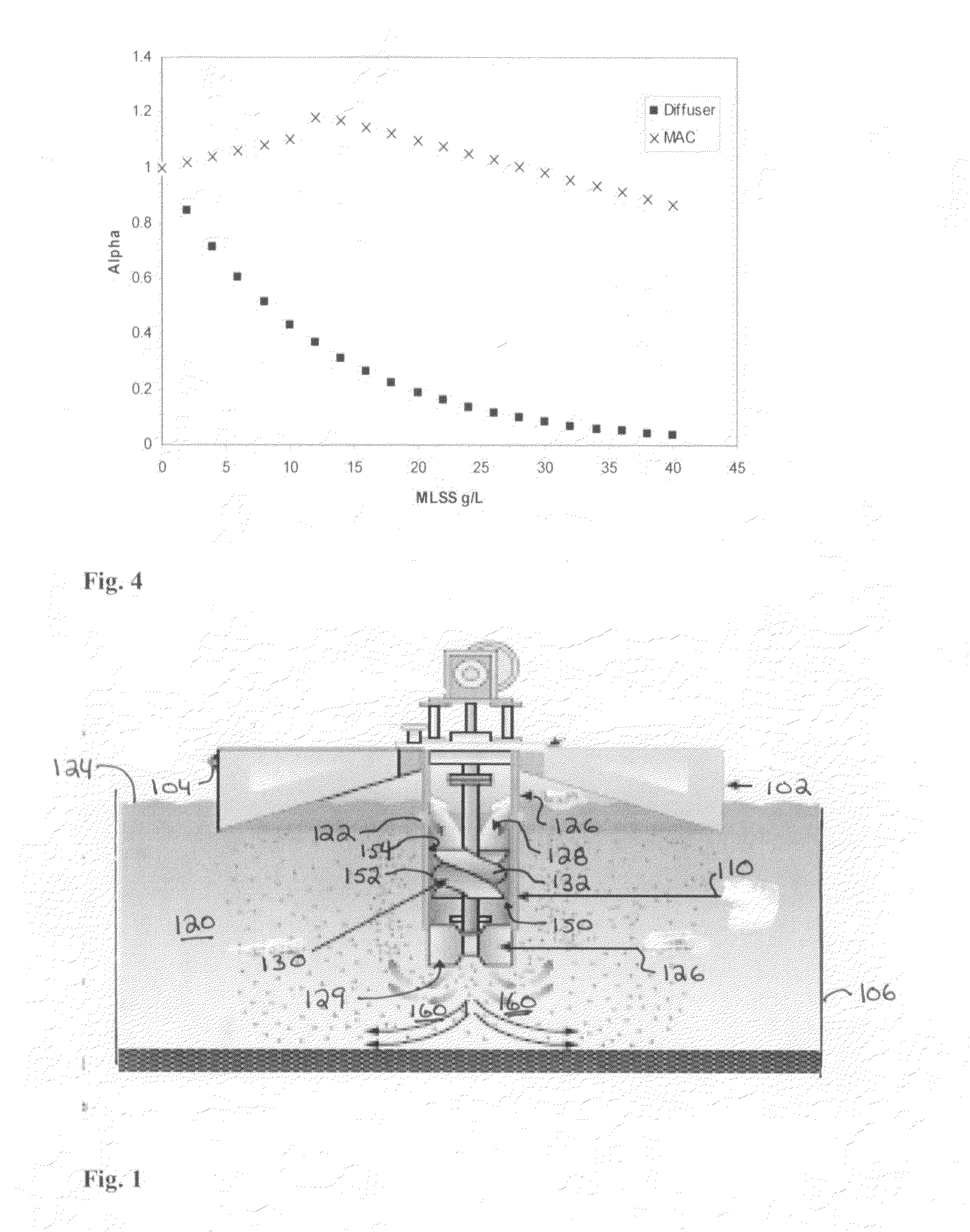
[0016]Turning now to FIG. 1, there is shown an embodiment of the invention using an in-situ oxygenator applied to an aerobic digester of a wastewater treatment system 100. As seen therein, the in-situ oxygenator includes a float assembly 102 having an anchor ring 104 which is placed in an aerobic digester 106 of a wastewater treatment system 100. In the present application, the material within the aerobic digester 106 is a high solid content material 120, typically on the order of greater than 10 grams per liter solids content, and more preferably between 10 and 40 grams per liter solids content. Extending in a downward orientation from the float assembly 102 is a draft tube 110. The draft tube 110 preferably has circumferential openings 122 located below the top surface 124 of the high-solids content material 120 in the aerobic digester 106. Baffles 126 are equilaterally spaced and symmetrically positioned around the openings 122 which are proximate to the entrance 128 to the draft...


PUM

PropertyMeasurementUnit
diameteraaaaaaaaaa
diameteraaaaaaaaaa
size distributionaaaaaaaaaa

Abstract

A system and method for oxygenating an aerobic sludge digester is provided. The disclosed embodiments include an aerobic sludge digester tank or vessel having a mechanically agitated contactor disposed therein, an oxygen injection subsystem adapted to inject oxygen into the digester tank proximate the mechanically agitated contactor. The embodiments of the mechanically agitated contactor include an agitator or impeller disposed within the draft tube which makes the draft tube the primary site for the gas-liquid mixing. In particular, the agitator or impeller is adapted to create gas bubbles having an average diameter between about 0.3 mm and 3.0 mm which are then dispersed into the aerobic digester. The mass transfer efficiency associated with the present system and method is enhanced from the combined effect of oxygen dissolution into the sludge and greater bubble residence time.

Description

CROSS REFERENCE TO RELATED APPLICATIONS[0001]This application is a continuation-in-part of U.S. patent application Ser. No. 11 / 602,519 filed Nov. 21, 2006, the disclosure of which is incorporated by reference herein.FIELD OF THE INVENTION[0002]The present invention relates to gas-liquid mixing operations, and more particularly, to a system and method for oxygenating high solid content material in an aerobic sludge digester.BACKGROUND[0003]Digestion in treatment of wastewater is a key process for the reduction of bio-solids and pathogen counts prior to any solids disposal. Most wastewater treatment plants employ some kind of digestion process with aerobic digestion of sludge becoming increasingly popular, in contrast to anaerobic digestion.[0004]Aerobic sludge digestion is one process that may be used to reduce both the organic content and the volume of the sludge. Under aerobic conditions, a large portion of the organic matter in sludge may be oxidized biologically by microorganisms...

Claims


Application Information

Patent Timeline
Patent Type & Authority Applications(United States)
IPC IPC(8): C02F3/22C02F11/02
CPCB01F3/04609B01F7/00358B01F7/0065B01F13/0049C02F3/206B01F2003/0468C02F3/02C02F3/1284C02F3/165B01F2003/0456Y02W10/10B01F23/23313B01F23/23363B01F23/23341B01F27/1132B01F27/1921B01F33/503C02F3/12C02F3/20B01F23/20B01F33/00
Inventor FABIYI, MALCOLM EZEKIELNOVAK, RICHARD A.
Owner PRAXAIR TECH INC
Learn More