Eureka AIR delivers breakthrough ideas for toughest innovation challenges, trusted by R&D personnel around the world.

Bridge scouring pit detection device

A technology of detection device and bridge pier, which is applied in the direction of measurement device, surveying and navigation, radio wave measurement system, etc., can solve the problems of a large number of manpower and material resources, ship turbulence, and high risk factor.

Active Publication Date: 2018-08-03
YANGZHOU UNIV
View PDF5 Cites 2 Cited by
  • Summary
  • Abstract
  • Description
  • Claims
  • Application Information

AI Technical Summary

Problems solved by technology

First of all, the current measurement methods carried by ships still require a lot of manpower and material resources, and the measurement cycle is long, so real-time measurement cannot be realized
Secondly, in order to ensure the smooth progress of the measurement work before the measurement, it is necessary to determine the local weather conditions, wind speed, water flow velocity, etc., especially during the flood season, the water flow around the piers to be measured is turbulent, and the risk factor of going to the area to be measured is extremely high. Not even reach the ship-through conditions, resulting in the inability to measure
Finally, in the actual measurement process, the ship will be bumped under the action of waves, which will affect the measurement effect of the ultrasonic range finder, causing the measurement result to be greater than the actual depth

Method used


Image

  • Bridge scouring pit detection device
  • Bridge scouring pit detection device
  • Bridge scouring pit detection device

Examples


Embodiment Construction

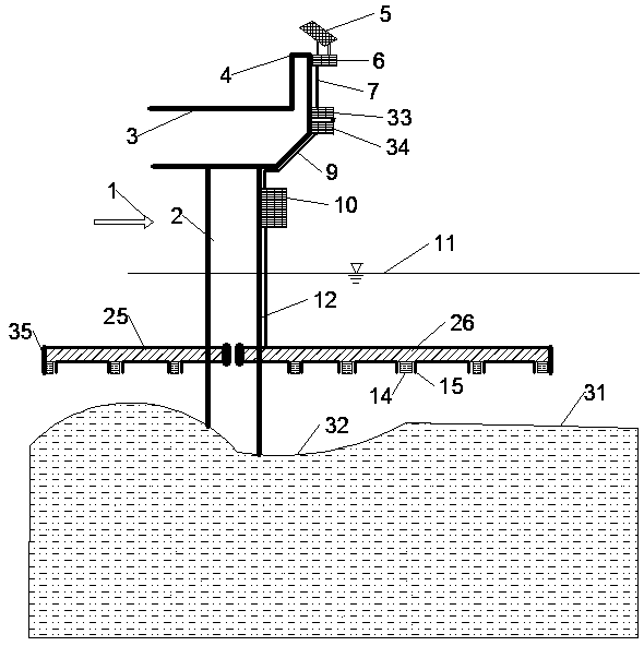
[0056] The present invention will be further described below in conjunction with the drawings and descriptions of the drawings.

[0057] A bridge pier scour detection device, including an underwater measurement device, an ultrasonic transmitter receiver, a control processing system, a positioning transmission system, and a power supply system;

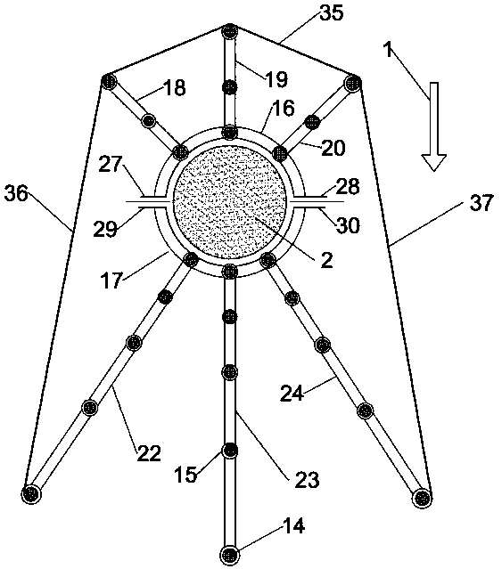
[0058]The underwater measuring device is composed of a bridge pier upstream device 25 , a bridge pier downstream device 26 , several small short metal pipes 15 , a first protective net 35 , a second protective net 36 and a third protective net 37 .

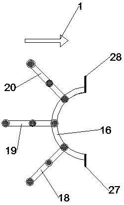
[0059] The pier upstream device 25 is composed of the first semicircular arc metal pipe 16, the first radial short metal pipe 18, the second radial short metal pipe 19, the third radial short metal pipe 20 and the first fixed metal sheet 27, The second fixed metal sheet 28 is combined; as Figure 3a shown.

[0060] The first radial metal short pipe 18, the second radial metal short pipe ...


PUM

PropertyMeasurementUnit
Lengthaaaaaaaaaa
Thicknessaaaaaaaaaa

Abstract

The invention provides a bridge scouring pit detection device. The bridge scouring pit detection device mainly comprises an underwater measuring device, an ultrasonic transmitting receiver, a controlprocessing system, a positioning transmission system and a power supply device, wherein the underwater measuring device is fixed on an underwater bridge; the ultrasonic transmitting receiver is fixedon the underwater measuring device; and the control processing system is used for controlling the ultrasonic transmitting receiver to measure the distance between the transmitting end of the ultrasonic transmitting receiver and the surface of a measured riverbed. Measured data are collected and transmitted to the bridge monitoring system of a bridge monitoring department through the positioning transmission system. The device can completely take the place of existing manpower ship measurement, solar energy is utilized for independent power supply, the transmission data can be measured in realtime, data simulation is carried out on the depths and distribution range of scouring pits, the purpose that the depths of the bridge scouring pits and the distribution status of the scouring pits aremonitored uninterruptedly in 24 hours is reached, the bridge monitoring department is helped to give out an early warning in flood seasons, and unnecessary loss of life and property is avoided.

Description

technical field [0001] The invention relates to a detection device for scour pits of bridge piers, which belongs to the technical field of detection of scour pit depths and scour ranges of bridge piers. Background technique [0002] With the rapid development of my country's modern transportation system, the number of bridges across rivers has increased year by year, and bridge disasters have occurred from time to time. According to statistics, transitional local scours around bridge piers, resulting in instability of bridge piers and bridge water damage, account for one-third of the causes of bridge accidents. The formation mechanism of local scour of bridge pier is due to the impact of water flow and vortex effect caused by the flow resistance of bridge pier, a three-dimensional boundary layer is separated around the pier, so that the local water flow with high turbulence and high velocity characteristics causes vortex and propagates downstream and The development produce...

Claims


Application Information

Patent Timeline
IPC IPC(8): G01S15/08G01C7/00
CPCG01C7/00G01S15/08Y02A90/30
Inventor 郭悬张琛于建兵唐站站
Owner YANGZHOU UNIV
Why Eureka
Eureka Blog
Learn More