Optical fiber ribbon dry-type bushing production method

A dry-type sleeve and production method technology, applied in the direction of fiber mechanical structure, etc., can solve the problems affecting the quality of splicing, affecting the normal transmission of optical cables, environmental pollution, etc., to overcome the instability of water blocking performance, ensure normal transmission performance, and excellent The effect of transmission performance

Inactive Publication Date: 2018-08-03
SHANTOU HIGH TECH ZONE AOXING OPTICAL COMM EQUIP
View PDF4 Cites 2 Cited by
  • Summary
  • Abstract
  • Description
  • Claims
  • Application Information

AI Technical Summary

Problems solved by technology

Whether it is an optical cable with an ointment-filled or semi-dry structure, it is inevitable to clean the ointment in the optical cable during cable construction, which not only brings inconvenience to the construction, affects the quality of the connection, but also causes pollution to the environment. Therefore, in recent years, Many customers, especially customers in overseas markets, have put forward the demand for fully dry structural ribbon cables
[0003] The optical fiber ribbon dry-type sleeve is an important component of the fully dry structural ribbon cable. In order to ensure the water-blocking performance of the sleeve, it is generally used to fill the sleeve with water-blocking powder, place water-blocking yarn or cover water-blocking tape. However, due to the insufficiency of the existing technology, water blocking powder and water blocking yarn cannot be evenly placed between the stacks of optical fiber ribbons in the sleeve, and the water blocking tape can only be wrapped on the stack of optical fiber ribbons. The outside of the tape matrix makes the water resistance of the casing unstable after production, and it is easy to see the longitudinal seepage of water between the overlapping ribbons of the optical fiber ribbons, which affects the normal transmission of the optical cable.

Method used


Image

  • Optical fiber ribbon dry-type bushing production method

Examples


Embodiment Construction

[0015] The idea, specific process flow and technical effects of the present invention will be further described below in conjunction with the accompanying drawings, so as to fully understand the purpose, characteristics and effects of the present invention.

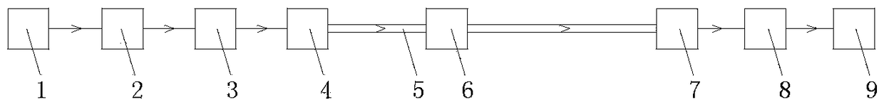
[0016] refer to figure 1 As shown, the present invention relates to a dry-type casing production method for an optical fiber ribbon, which has the following characteristics: after the optical fiber ribbon is released from the wire-releasing device 1, it passes through the ion generator 2, the water-blocking powder adding device 3, the extruder head 4, The cooling water tank 5, the excess length traction device 6, the blower 7, and the take-up traction device 8 arrive at the take-up device 9 to make an optical fiber ribbon dry sleeve.

[0017] Multiple optical fiber ribbons can be installed on the pay-off device 1 to provide a constant unwinding tension when the optical fiber ribbons are unwound, and can rotate in one dire...


PUM


Abstract

The invention discloses an optical fiber ribbon dry-type bushing production method, which is characterized in that optical fiber ribbons sequentially pass through an ion generator, a water-blocking powder adding device, an extruder head, a cooling water tank, an excess length traction device, a blow dryer and a wire take-up traction device to reach a wire take-up device after being paid off from awire pay-off device, thereby manufacturing an optical fiber ribbon dry-type bushing. According to the optical fiber ribbon dry-type bushing produced by adopting the optical fiber ribbon dry-type bushing production method, an appropriate amount of water-blocking powder are reserved on the periphery of an optical fiber ribbon stacking matrix in the bushing and between the optical fiber ribbons, thereby guaranteeing that the interior of the bushing has reliable water-blocking performance after production, and overcoming the defect of unstable water-blocking performance of the bushing after production in the prior art, such that an optical cable after cabling has the advantages of excellent transmission performance, mechanical performance and environmental performance.

Description

technical field [0001] The invention relates to the technical field of optical cable manufacturing, in particular to a method for producing an optical fiber ribbon dry-type sleeve. Background technique [0002] Ribbon optical cable is a large category of products in optical communication media. It has the characteristics of high fiber density and large number of cores. It is widely used in backbone network lines, and water resistance is an important performance index of optical cables. Ribbon optical cables According to different water-blocking materials, it can be divided into three types: ointment-filled type, semi-dry type and full-dry type. The grease-filled type refers to the structural type in which oil-filled paste is used to block water in both the casing and the cable core; the semi-dry type refers to the structural type in which the casing is filled with grease and the cable core uses dry water-blocking materials to block water; The fully dry type refers to the st...

Claims


Application Information

Patent Timeline
Patent Type & Authority Applications(China)
IPC IPC(8): G02B6/44
CPCG02B6/4479G02B6/448G02B6/44384
Inventor 陈列李钊杜少加庄经荣卢传远黄英伦
Owner SHANTOU HIGH TECH ZONE AOXING OPTICAL COMM EQUIP
Why Eureka
Try Eureka