OLED display device

A technology for display devices and display areas, applied to electrical components, casings/cabinets/drawer parts, electric solid devices, etc., can solve the influence of thickness and frame width, and the connection between flexible printed circuit boards and bottom plates Eliminate peeling, high cost and other problems, achieve the effect of improving bonding stability, reducing the risk of peeling, and easy bonding

Inactive Publication Date: 2018-08-03
AU OPTRONICS CORP
View PDF0 Cites 2 Cited by
  • Summary
  • Abstract
  • Description
  • Claims
  • Application Information

AI Technical Summary

Problems solved by technology

[0004] In the prior art, in order to ensure the impact of bending action on product reliability, the materials used for flexible printed circuit boards must use relatively bending-resistant and high-cost materials
In addition, some space must be reserved during the bending process, which will also affect the thickness of the finished product and the width of the frame; after the flexible printed circuit board is bent, it will also generate a large pulling force on the electrical connection, and may even The connection between the flexible printed circuit board and the base plate is caused to peel off, which makes the bonding stability of the flexible printed circuit board low and affects the performance of OLED display

Method used


Image

  • OLED display device
  • OLED display device
  • OLED display device

Examples


Embodiment Construction

[0028] In order to have a further understanding of the purpose, structure, features, and functions of the present invention, the following detailed descriptions are provided in conjunction with the embodiments.

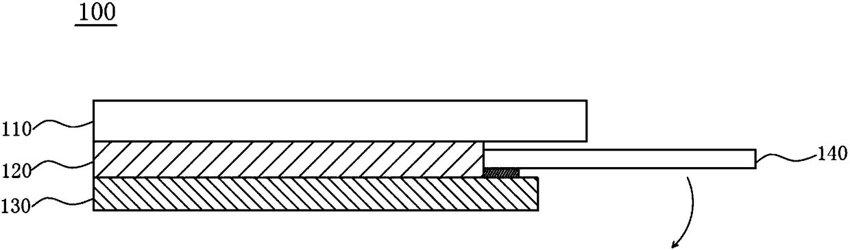
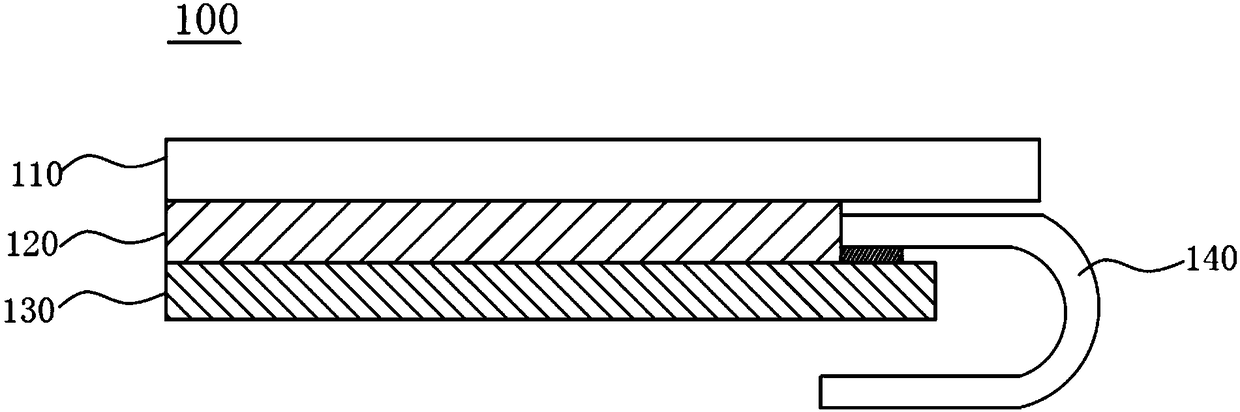
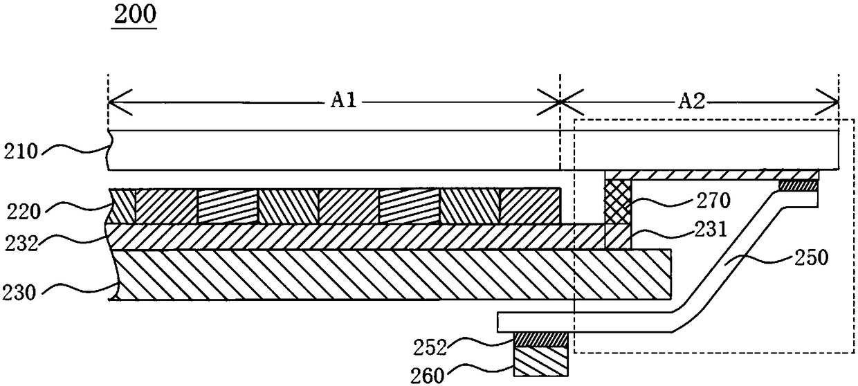
[0029] Please also see image 3 and Figure 4 , image 3 is a partial cross-sectional view of the OLED display device of the present invention; Figure 4 for image 3 A partial enlarged view of the OLED display device in the middle. The OLED display device 200 of the present invention includes a base plate 230 and a cover plate 210 , and the base plate 230 is disposed opposite to the cover plate 210 . The bottom plate 230 includes two opposite surfaces. The surface of the bottom plate 230 close to the cover plate 210 is defined as a first surface S1 , and the surface of the bottom plate 230 away from the cover plate 210 is defined as a second surface S2 . The OLED display device 200 of the present invention further includes an OLED light-emitting component 220, w...


PUM


Abstract

The invention discloses an OLED display device. The OLED display device comprises a bottom plate and a cover plate which are opposite, and the bottom plate is provided with a first surface and a second surface which are opposite. The OLED display device further comprises a display area, a non-display area, an OLED light-emitting assembly, first electrodes, second electrodes, conductive protrusionsand a flexible printed circuit board, wherein the OLED light-emitting assembly is arranged on the first surface of the bottom plate; the first electrodes are arranged on the first surface of the bottom plate and located in the non-display area; the second electrodes are arranged on the cover plate and located in the non-display area; the conductive protrusions are arranged between the bottom plate and the cover plate and are electrically connected with the first electrodes and the second electrodes respectively; the flexible printed circuit board is provided with a first end and a second endwhich are opposite, the first end is electrically connected with the second electrodes, and the second end extends to the side, wherein the second surface is located, of the bottom plate. According tothe OLED display device, the risk that the flexible printed circuit board is peeled off is reduced, and the fitting stability of the flexible printed circuit board is improved.

Description

technical field [0001] The invention relates to an OLED display device, in particular to an OLED display device which improves the bonding stability of a flexible printed circuit board. Background technique [0002] OLED display device is a display element with high brightness, high response speed, thin and short, full color, no viewing angle difference, and no need for backlight. It has gradually replaced TN (twisted nematic) and STN (super twisted nematic) The LCD panel module market will further pose a threat to the small-sized TFT-LCD market, and it will be applied to the display screens of portable information products such as mobile phones, personal digital assistants, and even notebook computers. [0003] Please refer to figure 1 and figure 2 , figure 1 It is an unbent cross-sectional view of a flexible printed circuit board when an OLED display device is assembled in the prior art; figure 2 It is a cross-sectional view of a flexible printed circuit board after ...

Claims


Application Information

Patent Timeline
Patent Type & Authority Applications(China)
IPC IPC(8): H01L27/32H05K5/02H05K5/03
CPCH05K5/0204H05K5/03H10K59/00
Inventor 林国栋陈宪泓
Owner AU OPTRONICS CORP
Why Eureka
Try Eureka