Reactive voltage control method based on source network coordination

A voltage control method and source network technology, applied in AC network voltage adjustment, reactive power compensation, AC network circuits, etc., can solve problems such as voltage fluctuations

Pending Publication Date: 2018-08-03
NORTH CHINA ELECTRIC POWER UNIV (BAODING) +4
View PDF5 Cites 7 Cited by
  • Summary
  • Abstract
  • Description
  • Claims
  • Application Information

AI Technical Summary

Problems solved by technology

[0005] Aiming at the deficiencies of the prior art, the purpose of the present invention is to provide a reactive voltage control method based on source-network coordination, which is used to solve the voltage fluctuation problem caused by wind power changes and provide reference for power grid operation.

Method used


Image

  • Reactive voltage control method based on source network coordination
  • Reactive voltage control method based on source network coordination
  • Reactive voltage control method based on source network coordination

Examples


Embodiment 1

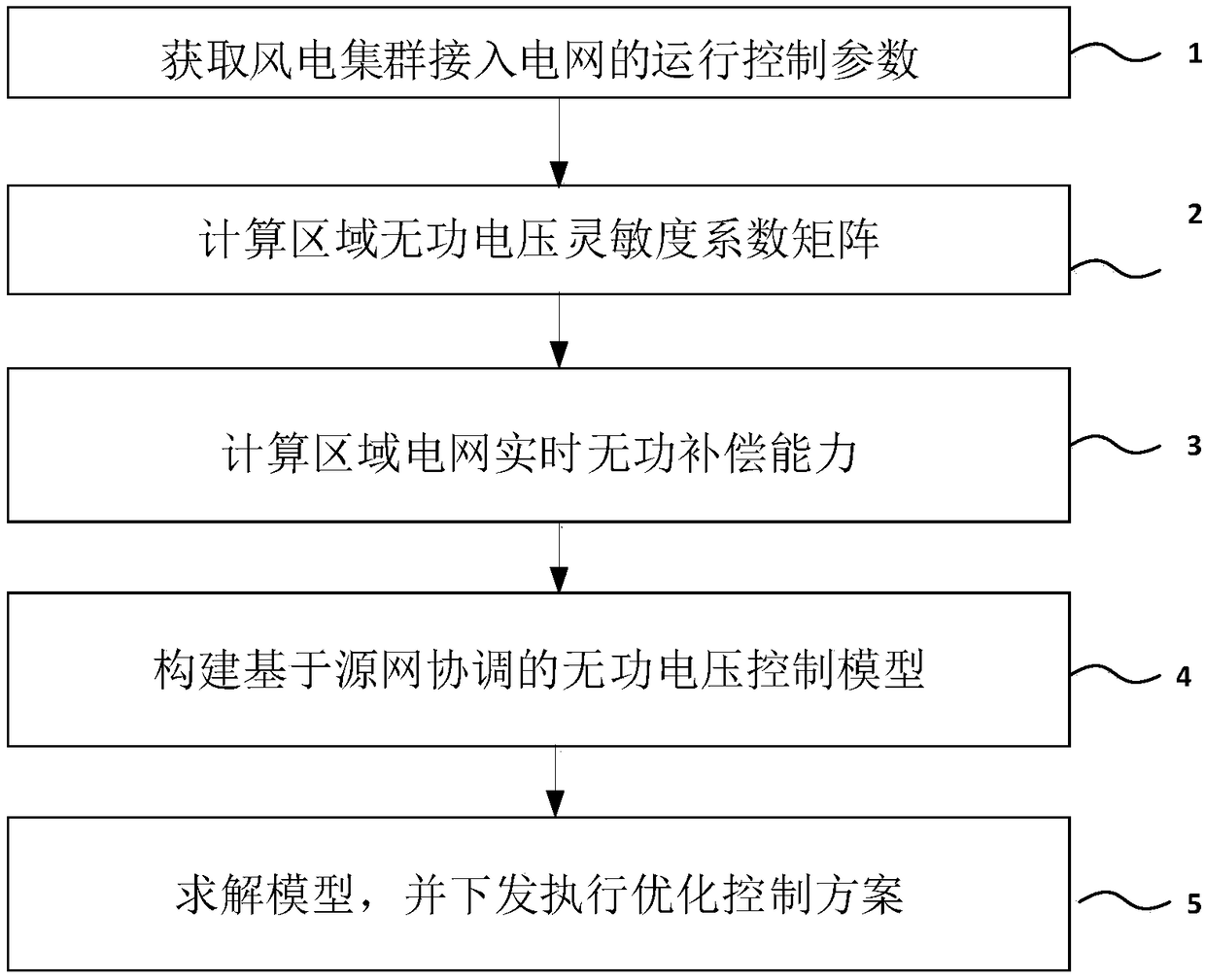
[0035] figure 1 It is a flowchart of a reactive voltage control method based on source-network coordination. figure 1 Among them, a flow chart of a reactive power voltage control method based on source-network coordination provided by the present invention includes:

[0036] S1: Obtain the operation control parameters of the wind power cluster connected to the grid;

[0037] S2: Calculate the regional reactive voltage sensitivity coefficient matrix;

[0038] S3: Calculate the reactive power compensation capability of the reactive power compensation device in the area;

[0039] S4: Build a reactive power optimization control model based on source-network coordination

[0040] S5: Solve and obtain the reactive power and voltage control scheme coordinated by the source network, and issue it for execution.

[0041] Described S1 comprises the following steps:

[0042] S101: Obtain the network structure parameters of large-scale wind power centralized access to the regional pow...

Embodiment 2

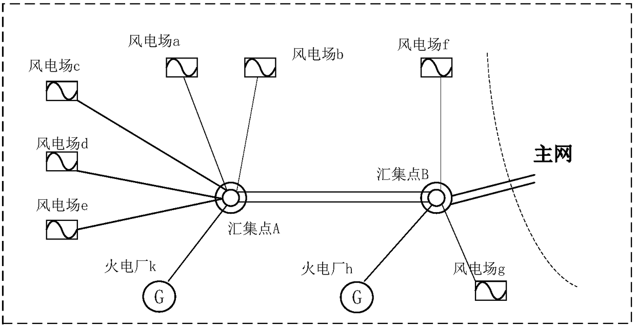
[0088] figure 2 It is a schematic diagram of a regional grid where wind power is centrally connected. Taking this as an example, the present invention provides a reactive power and voltage control method based on source-network coordination:

[0089] S1: Obtain grid parameters

[0090] In the regional power grid, there are two 330kV substations, seven wind farms, and two thermal power plants, of which the installed capacity of wind power is 1000MW and conventional power supply. Among them, wind farms a-e are collected to the low-voltage side of substation A (110kV), thermal power plant k is connected to the high-voltage side of substation A (330KV); wind farms g and f are collected to the low-voltage side of substation B (110KV), thermal power plant h Connect to the high voltage side (330KV) of substation B. Wind power is collected by substations A and B and sent to the main grid. In the regional power grid, discrete reactive power compensation devices (capacitors / reactors...


PUM


Abstract

The invention discloses a reactive voltage control method based on source network coordination in the field of wind power cluster grid-connected control. The method comprises that an operation controlparameter of a wind power cluster accesses the power grid is obtained; a reactive voltage sensitivity coefficient matrix of the regional power grid is calculated; a reactive compensation capability of a reactive power compensator in the region is calculated; a source network coordinated reactive voltage optimized control model adapted to the wind power cluster grid connection is constructed; anda source network coordinated reactive voltage control scheme is obtained by solution and issued for execution. According to the method, voltage fluctuation of a wind farm cluster is inhibited via source network coordinated control, and the wind power absorption capability of the power grid is improved further.

Description

technical field [0001] The invention belongs to the technical field of large-scale wind power grid-connected control, and in particular relates to a reactive power voltage control method based on source-network coordination. Background technique [0002] With the rapid increase of wind power installed capacity in large-scale 10-million-kilowatt wind power bases, the proportion of wind power access has increased sharply, and the impact of random fluctuations in wind power power on grid voltage cannot be ignored. [0003] At present, domestic and foreign scholars have done a lot of research on the corresponding control methods for the problem of voltage fluctuations caused by active power fluctuations of wind farms / groups, mainly by studying the control strategies of reactive power compensation devices installed by wind turbines themselves. The reactive power compensation equipment first performs rough adjustment, and then arranges continuous reactive power compensation equipm...

Claims


Application Information

Patent Timeline
Patent Type & Authority Applications(China)
IPC IPC(8): H02J3/16H02J3/38
CPCH02J3/386H02J3/16H02J2203/20Y02E10/76Y02E40/30
Inventor 张尧翔刘文颖王维洲夏鹏梁琛朱丹丹华夏姚春晓史玉杰蔡万通药炜张雨薇刘福潮王方雨郑晶晶郭虎彭晶田浩韩永军吕良曾文伟王贤许春蕾荣俊杰李宛齐聂雅楠冉忠
Owner NORTH CHINA ELECTRIC POWER UNIV (BAODING)
Why Eureka
Try Eureka