Method and device for indicating and determining synchronization block, base station and user equipment

A technology for user equipment and synchronization blocks, which is applied to synchronization devices, error prevention/detection using return channels, wireless communication, etc., and can solve problems such as large bit overhead.

Active Publication Date: 2018-08-03
BEIJING XIAOMI MOBILE SOFTWARE CO LTD
View PDF4 Cites 12 Cited by
  • Summary
  • Abstract
  • Description
  • Claims
  • Application Information

AI Technical Summary

Problems solved by technology

[0004] In related technologies, a bitmap (bitmap) is used to indicate which beam's SSB is sent and which beam's SSB is not sent, and the bit overhead is large

Method used


Image

  • Method and device for indicating and determining synchronization block, base station and user equipment
  • Method and device for indicating and determining synchronization block, base station and user equipment
  • Method and device for indicating and determining synchronization block, base station and user equipment

Examples


Embodiment Construction

[0059] Reference will now be made in detail to the exemplary embodiments, examples of which are illustrated in the accompanying drawings. When the following description refers to the accompanying drawings, the same numerals in different drawings refer to the same or similar elements unless otherwise indicated. The implementations described in the following exemplary examples do not represent all implementations consistent with the present invention. Rather, they are merely examples of apparatuses and methods consistent with aspects of the invention as recited in the appended claims.

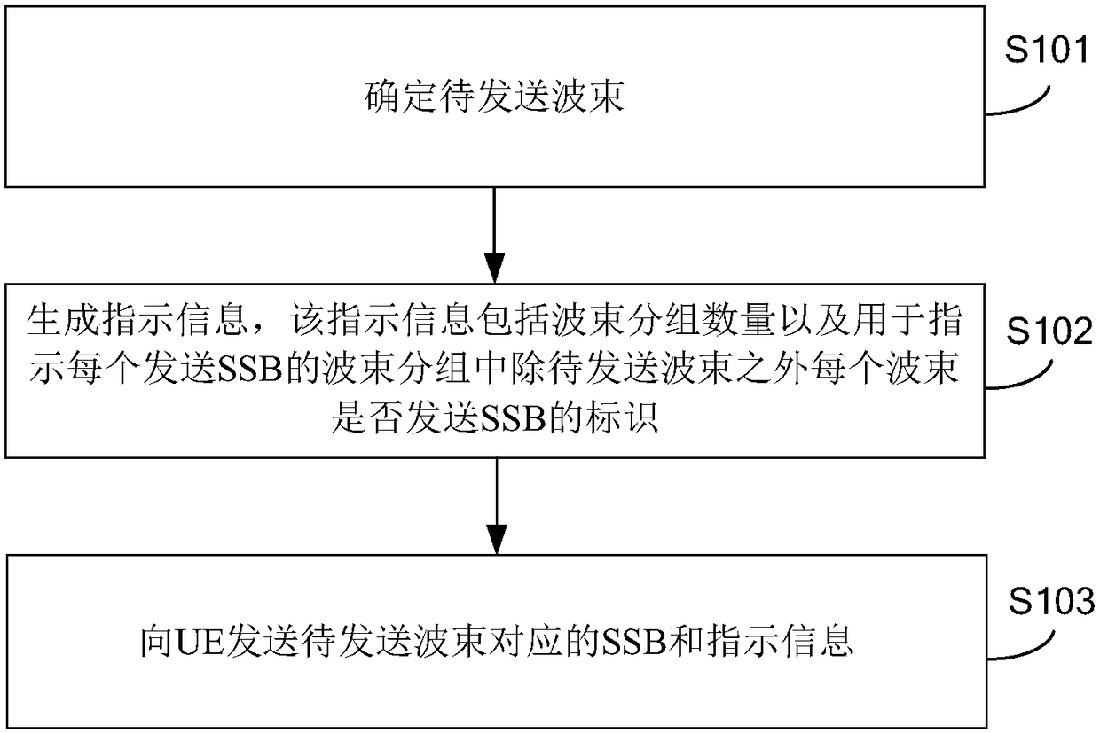
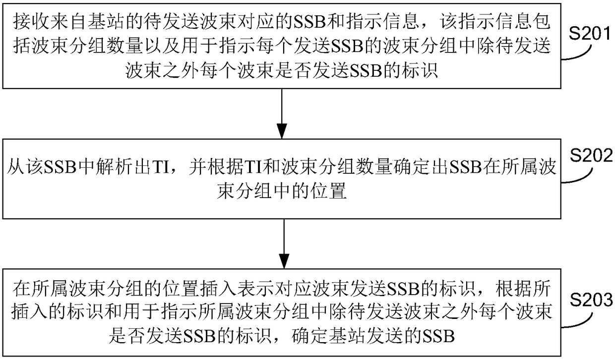
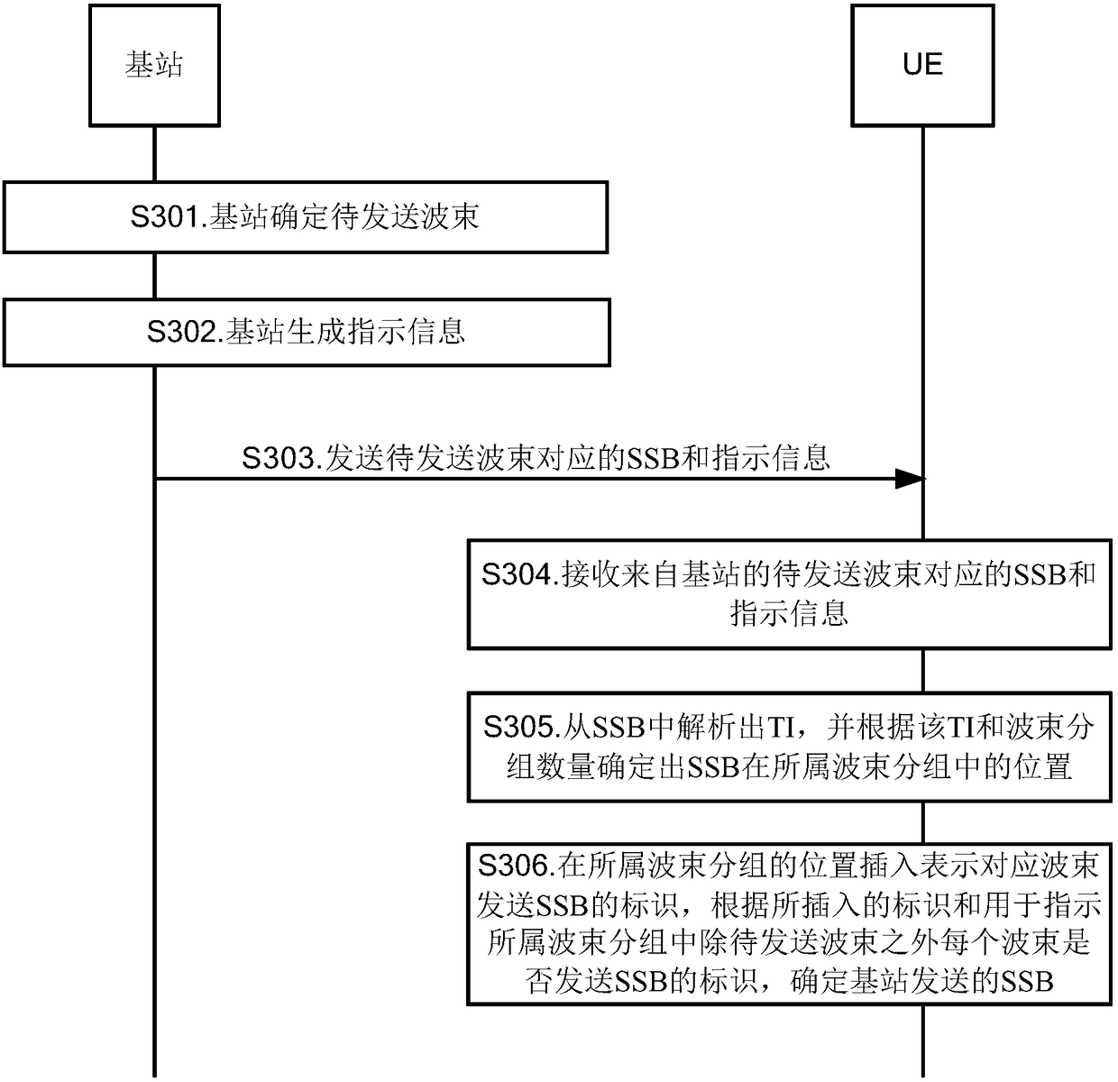
[0060] figure 1 is a flow chart of a synchronization block indication method shown in an exemplary embodiment of the present application. This embodiment is described from the base station side, as figure 1 As shown, the indication method of the synchronization block includes:

[0061] In step S101, a beam to be transmitted is determined.

[0062] In this embodiment, the base station may dete...


PUM


Abstract

The present disclosure relates to a method and device for indicating and determining a synchronization block, a base station, user equipment, and a computer readable storage medium. The method comprises the steps: determining a beam to be transmitted; generating indication information, wherein the indication information includes a number of beam packets, and identifications for indicating whethereach beam of the beam packet of each transmission synchronization signal block SSB, other than the to-be-transmitted beam, sends an identifier of the SSB or not; sending the SSB and the indication information corresponding to the to-be-sent beam to the user equipment. The above embodiment can reduce the bit overhead and flexibly represent the SSB sent by the base station.

Description

technical field [0001] The present disclosure relates to the field of communication technologies, and in particular to a synchronization block indication and determination method, device, base station, user equipment, and computer-readable storage medium. Background technique [0002] With the rapid development of wireless communication technology, a fifth generation mobile communication technology (5th Generation, 5G for short) system appears. The 5G system will be oriented to high-band applications, that is, applications in frequency bands above 6GHz. In the high frequency band, because the propagation characteristics of radio waves are not good, the traditional omnidirectional transmission will no longer be applicable, and it is necessary to introduce beam scanning and beam management for communication. [0003] In the recent 3rd Generation Partnership Project (3GPP) discussion, it was agreed to send the synchronization signal block (SSB) of the default beam. However, in...

Claims


Application Information

Patent Timeline
IPC IPC(8): H04L1/16H04B7/06H04W56/00
CPCH04B7/0617H04L1/1614H04W56/00H04B7/0695H04B7/0408H04W56/001H04W72/0446H04W84/042
Inventor 刘洋
Owner BEIJING XIAOMI MOBILE SOFTWARE CO LTD
Why Eureka
Try Eureka