Heating and cooking system, induction heating cooker, and electric apparatus

An electrical equipment and induction heating technology, which is applied to induction heating, induction heating devices, vessels with integral electric heating devices, etc., can solve problems such as inability to use induction heating coils at the same time

Inactive Publication Date: 2018-08-03
MITSUBISHI ELECTRIC CORP +1
View PDF13 Cites 4 Cited by
  • Summary
  • Abstract
  • Description
  • Claims
  • Application Information

AI Technical Summary

Problems solved by technology

Therefore, there is a problem that induction heating by the induction heating coil and heating by electric power received from the power supply coil through non-contact power transmission cannot be performed simultaneously.

Method used


Image

  • Heating and cooking system, induction heating cooker, and electric apparatus
  • Heating and cooking system, induction heating cooker, and electric apparatus
  • Heating and cooking system, induction heating cooker, and electric apparatus

Examples


Embodiment approach 1

[0032] (structure)

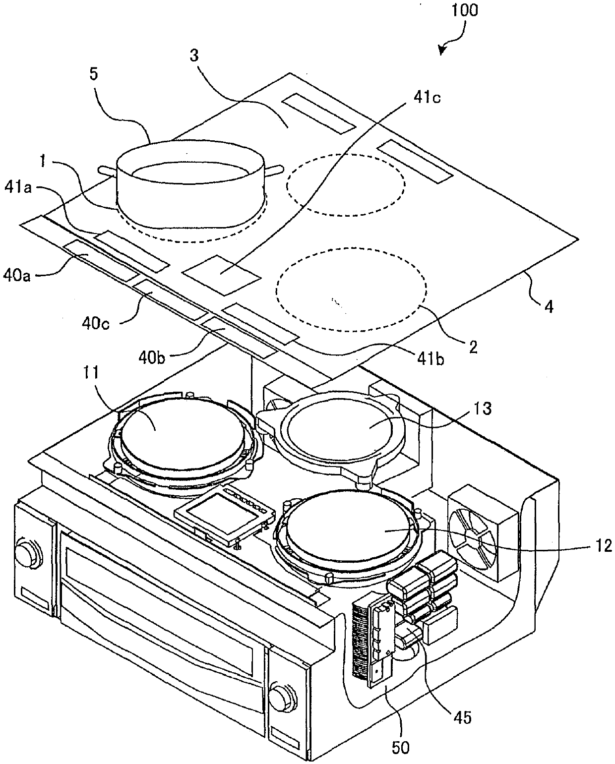
[0033] figure 1 It is an exploded perspective view showing the main body of the induction heating cooker in the heating cooking system of Embodiment 1.

[0034] Such as figure 1 As shown, the upper part of the main body 100 of the induction heating cooker has a top plate 4 on which a load to be heated 5 such as a pan or an electric device 200 is placed. description in figure 1 An example in which an object to be heated 5 is placed as a load is shown in FIG. The top plate 4 is equipped with a first heating port 1, a second heating port 2, and a third heating port 3 as heating ports for inductively heating an object to be heated 5, and a first heating unit 11, a first heating unit 11, and a second heating unit are arranged corresponding to each heating port. 2. The heating unit 12 and the third heating unit 13 can place the object to be heated 5 on each heating opening to perform induction heating.

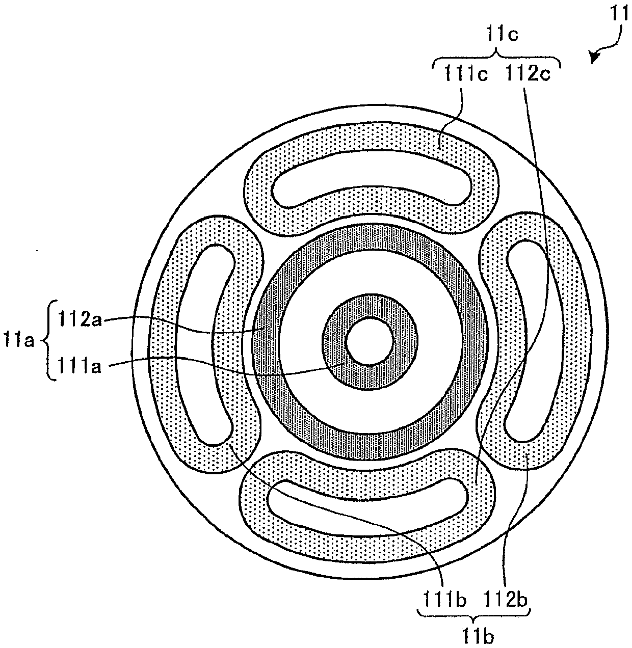
[0035] In Embodiment 1, the first heating unit 11 and...

Deformed example 1

[0123] A modified example of the power receiving coil 65 will be described.

[0124] Figure 7 , Figure 8 It is a figure explaining the modification of the power receiving coil of the electric equipment of Embodiment 1.

[0125] The power receiving coil 65 in this modified example includes an annular conductor 300 , a coil 310 , and a magnetic body 320 . In addition, in Figure 8 In , the illustration of the magnetic body 320 is omitted.

[0126] The annular conductor 300 is formed of a conductive material such as a metal having low resistance such as aluminum or copper. The annular conductor 300 is formed by bending the annular conductor 300 in the middle of the longitudinal direction in a right-angled direction after processing an aluminum plate or a copper plate, etc., into a ring shape forming an electrically closed closed circuit, for example, by cutting or pressing. It is L-shaped. The annular conductor 300 has a horizontal portion 301 disposed on the bottom surfa...

Deformed example 2

[0137] Next, another configuration example of the drive circuit 50 will be described.

[0138] Figure 9 It is a figure which shows another drive circuit of the induction heating cooker of Embodiment 1.

[0139] Figure 9 The driver circuit 50a shown is equipped for Figure 4 The inverter circuit 23 is a so-called full-bridge inverter in which IGBTs 232a and 232b as switching elements and diodes 232c and 232d as freewheeling diodes are additionally connected. In addition, other structures with Figure 4 Same, attach the same symbol to the same part.

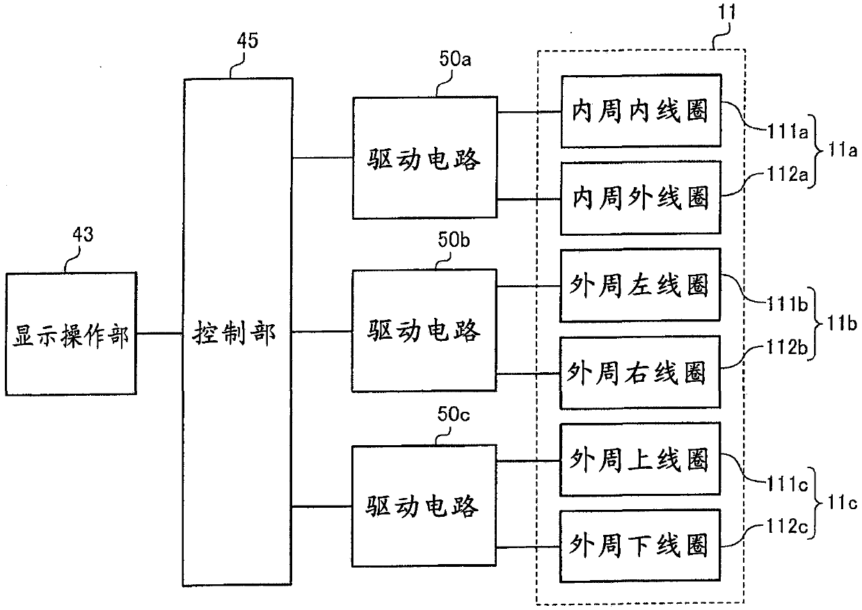
[0140] The control unit 45 outputs drive signals for driving the respective switching elements (IGBTs 231a, 231b, 232a, and 232b) of the inverter circuit 23, and controls so that the power output to the inner peripheral coil 11a becomes a heating operation similarly to the above operation. The power set in . Also in such a configuration, the same effect can be obtained.

[0141] In addition, in Figure 9 In the example of...


PUM


Abstract

A heating and cooking system of the present invention is provided with: a first coil that generates a first high-frequency magnetic field by being supplied with a first high-frequency current; a firstinverter circuit that supplies the first high-frequency current to the first coil; a first heat generating body, which is disposed in the first high-frequency magnetic field of the first coil, and which is inductively heated by means of the first coil; a second coil that generates a second high-frequency magnetic field by being supplied with a second high-frequency current; a second inverter circuit, which is provided separately from the first inverter circuit, and which supplies the second high-frequency current to the second coil; a power receiving coil, which is disposed in the second high-frequency magnetic field of the second coil, and which receives power from the second coil; and a second heat generating body that generates heat by means of the power received by the power receivingcoil.

Description

technical field [0001] The present invention relates to a heating cooking system using induction heating and heating based on non-contact power transmission, an induction heating cooker, and electric equipment. Background technique [0002] In a conventional high-frequency induction heating cooker, a proposal has been proposed that includes an induction heating coil for inductively heating a cooking vessel, a power receiving coil that receives electricity from a power supply coil, and a heating unit. In magnetic induction, the heating unit is energized by a power receiving coil, and the induction heating coil and the power supply unit of the power supply coil are shared (for example, refer to Patent Document 1). [0003] prior art literature [0004] Patent Document 1: Japanese Patent Application Laid-Open No. 4-341790 Contents of the invention [0005] In a conventional high-frequency induction heating cooker, a power supply unit that energizes a heating coil and a powe...

Claims


Application Information

Patent Timeline
IPC IPC(8): H05B6/12
CPCA47J37/0629A47J27/004H05B6/1236H05B6/062Y02B40/00H05B6/1272H05B6/1281H02J50/10H05B6/065H05B6/1209H05B11/00H05B6/12H05B6/1245
Inventor 吉野勇人文屋润菅郁朗竹下美由纪龟冈和裕
Owner MITSUBISHI ELECTRIC CORP
Why Eureka
Try Eureka