Ear pressure balance adjusting device

A technology of balance regulation and pressure, applied in earplugs, ear therapy, etc., can solve problems such as poor ear pressure regulation, difficulty in achieving pressure balance, and ear discomfort of patients, so as to improve comfort and avoid instantaneous impact.

Inactive Publication Date: 2018-08-07
FOSHAN HAIZHUORUI FLUID CONTROL ENG
View PDF0 Cites 3 Cited by
  • Summary
  • Abstract
  • Description
  • Claims
  • Application Information

AI Technical Summary

Problems solved by technology

Similarly, because the cavity of the middle ear part inside the eardrum communicates with the Eustachian tube, and the Eustachian tube is relatively narrow and long, and has a one-way valve-like structure, when the pressure in the hyperbaric oxygen chamber changes, the two sides of the eardrum The pressure on one side is difficult to balance, causing

Method used


Image

  • Ear pressure balance adjusting device
  • Ear pressure balance adjusting device
  • Ear pressure balance adjusting device

Examples


Embodiment 1

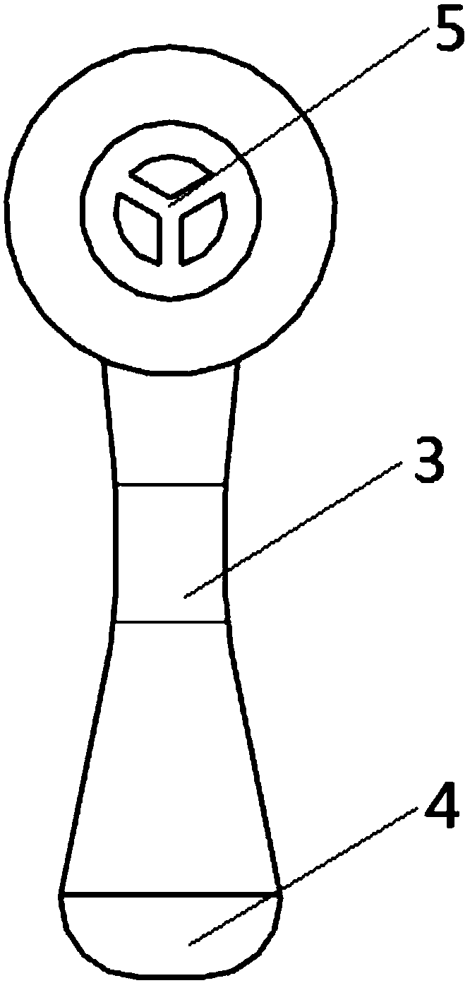
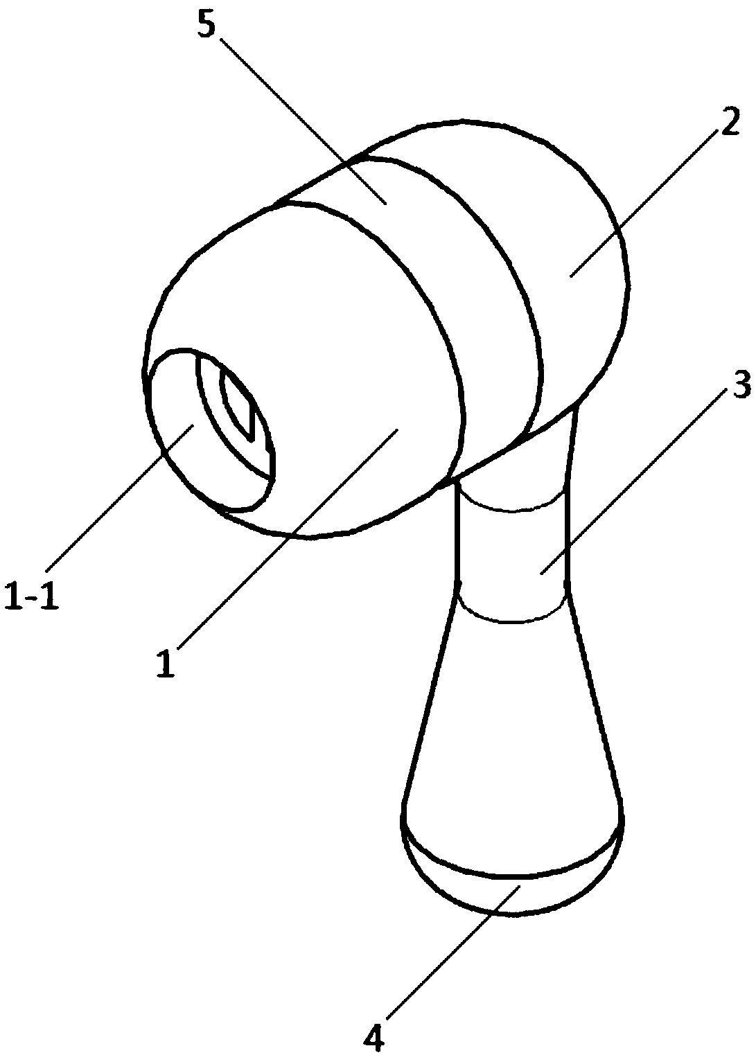
[0035] see Figure 1-Figure 8 , an ear pressure balance adjustment device in this embodiment, comprising an earplug part that blocks the outer ear and an adjustment part 3 connected to the earplug part; wherein, the inside of the earplug part is provided with a transition cavity that communicates with the external auditory canal, The inside of the adjustment part 3 is provided with a balance cavity, one end of which is connected to the transition cavity, and the other end is connected to the external atmosphere; the balance cavity is provided with a gas flow restriction structure for reducing the airflow velocity.

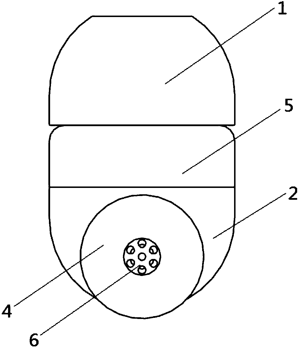
[0036] see Figure 4 and Figure 6 , the gas flow restriction structure includes a ball valve body 6 arranged in the regulating part 3, the balance cavity has an intermediate cavity for accommodating the ball valve body 6, the diameter of the intermediate cavity is larger than the diameter of the ball valve body 6, the The ball valve body 6 is provided with sever...

Embodiment 2

[0051] see Figure 7 The difference between this embodiment and Embodiment 1 is that the gas flow restricting structure is formed by an elastic narrowing hole 7 arranged in the adjustment part 3, and the side wall of the elastic narrowing hole 7 is made of elastic material The elastic wall body, the balance cavity leading from the elastic narrowing hole 7 to the outside gradually increases, and the balance cavity leading from the elastic narrowing hole 7 to the transition cavity gradually increases.

[0052] The working principle of the above-mentioned gas flow restriction structure is: when the aircraft takes off, the cabin pressure gradually decreases, and the gas flows from the external auditory canal through the transition cavity and the balance cavity to the outside. When the gas flows to the elastic narrowing hole 7, due to the aperture becomes smaller, so the gas is blocked and the outflow speed becomes slower. Since the side wall of the elastic narrowing hole 7 is made...

Embodiment 3

[0054] see Figure 8 The difference between this embodiment and Embodiment 1 is that: the upper transition port 9 is set as a vertical channel, and the vertical channel communicates with the transition cavity. Setting such an upper transition port 9 has a simple structure and is convenient for manufacture.


PUM


Abstract

The invention discloses an ear pressure balance adjusting device. The ear pressure balance adjusting device comprises an earplug part and an adjusting part, wherein the earplug part is used for plugging an external ear; the adjusting part is connected with the earplug part; the interior of the earplug part is provided with a transition cavity which is communicated with an external auditory meatus;the interior of the adjusting part is provided with a balance cavity, one end of the balance cavity is connected with the transition cavity, and the other end of the balance cavity is connected withexternal atmosphere; an air flowing limiting structure is arranged in the balance cavity and is used for reducing the speed of air flow. The ear pressure balance adjusting device has the advantages that by arranging the air flowing limiting structure for simulating air flow characteristics of auditory tubes, the speeds of air flows in the cavities of two sides of an ear drum are approximately thesame during takeoff and landing of an aircraft, the pressures at both sides of the ear drum are maintained balance, and the discomfort of the ears is greatly decreased; the ear pressure balance adjusting device can be used for a patient in a high-pressure oxygen cabin, and the discomfort of the ears due to pressure change in the high-pressure oxygen cabin is avoided.

Description

technical field [0001] The invention relates to an ear adjustment device, in particular to an ear pressure balance adjustment device. Background technique [0002] With the development of science and technology and economy, air travel has become common. However, problems such as tinnitus and earache caused by pressure changes are becoming more and more prominent during the flight. The reason is that the cockpit pressure changes during takeoff and landing, and the pressure on both sides of the eardrum in the ear is inconsistent, which causes the eardrum to be compressed and causes discomfort. The inconsistency of the pressure on both sides of the eardrum is caused by the ear itself. It is caused by physiological structural characteristics. Specifically, the external auditory canal on the outer side of the eardrum is relatively open. When the cabin pressure changes, it is easier for gas to enter and exit the external auditory canal, and the air pressure balance can be quickly ...

Claims


Application Information

Patent Timeline
IPC IPC(8): A61F11/08
CPCA61F11/08A61F11/085
Inventor 刘亚俊张智敏梁卫平
Owner FOSHAN HAIZHUORUI FLUID CONTROL ENG
Why Eureka
Try Eureka