Plate cutting saw air-floating-type worktable and plate cutting method
A workbench, air-floating technology, applied in sawing machine devices, manufacturing tools, metal sawing equipment, etc., can solve the problem of easily scratching the surface of the plate, and achieve the effect of not easily scratching and protecting the plate
- Summary
- Abstract
- Description
- Claims
- Application Information
AI Technical Summary
Problems solved by technology
Method used
Image

Examples
Embodiment Construction
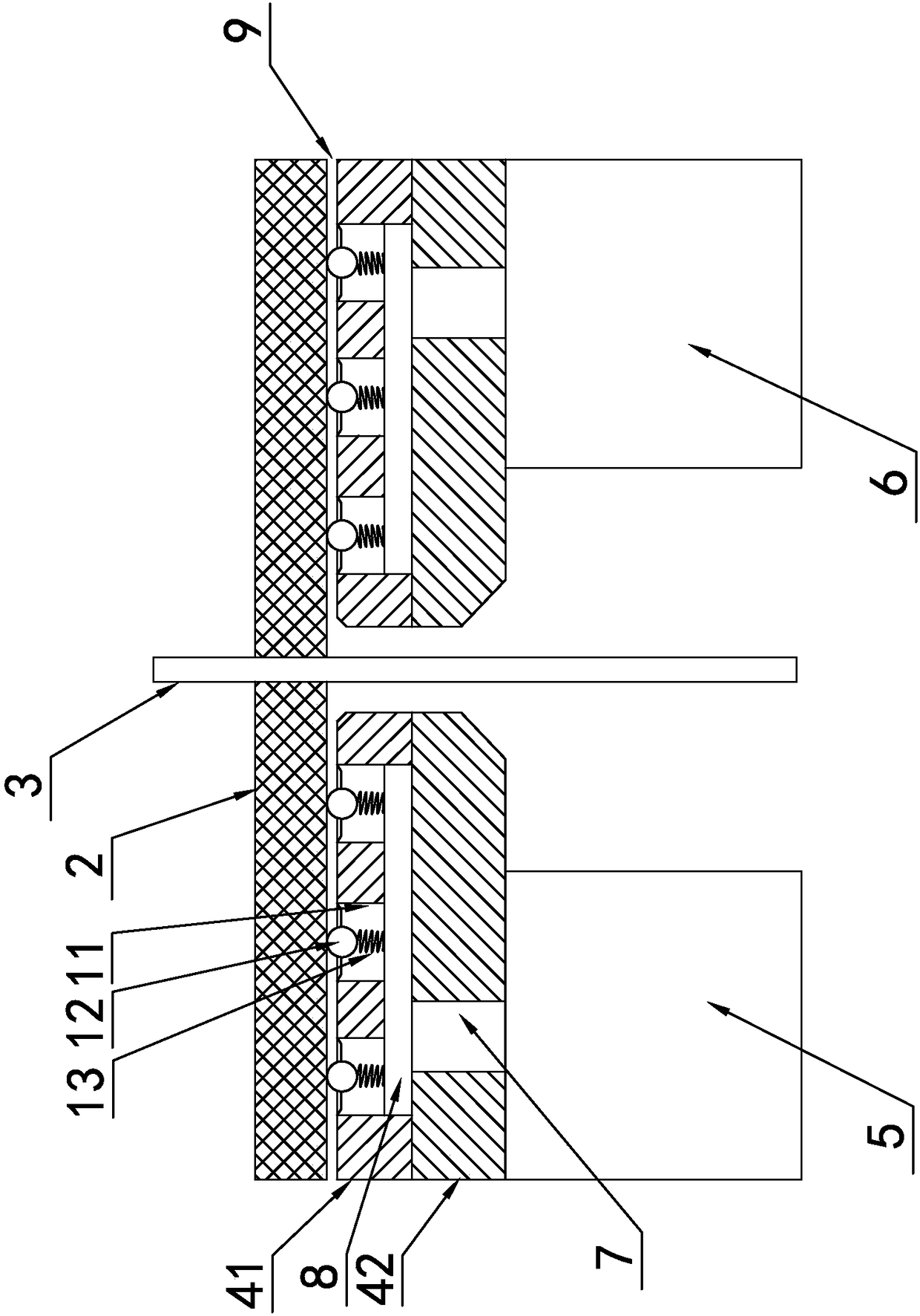
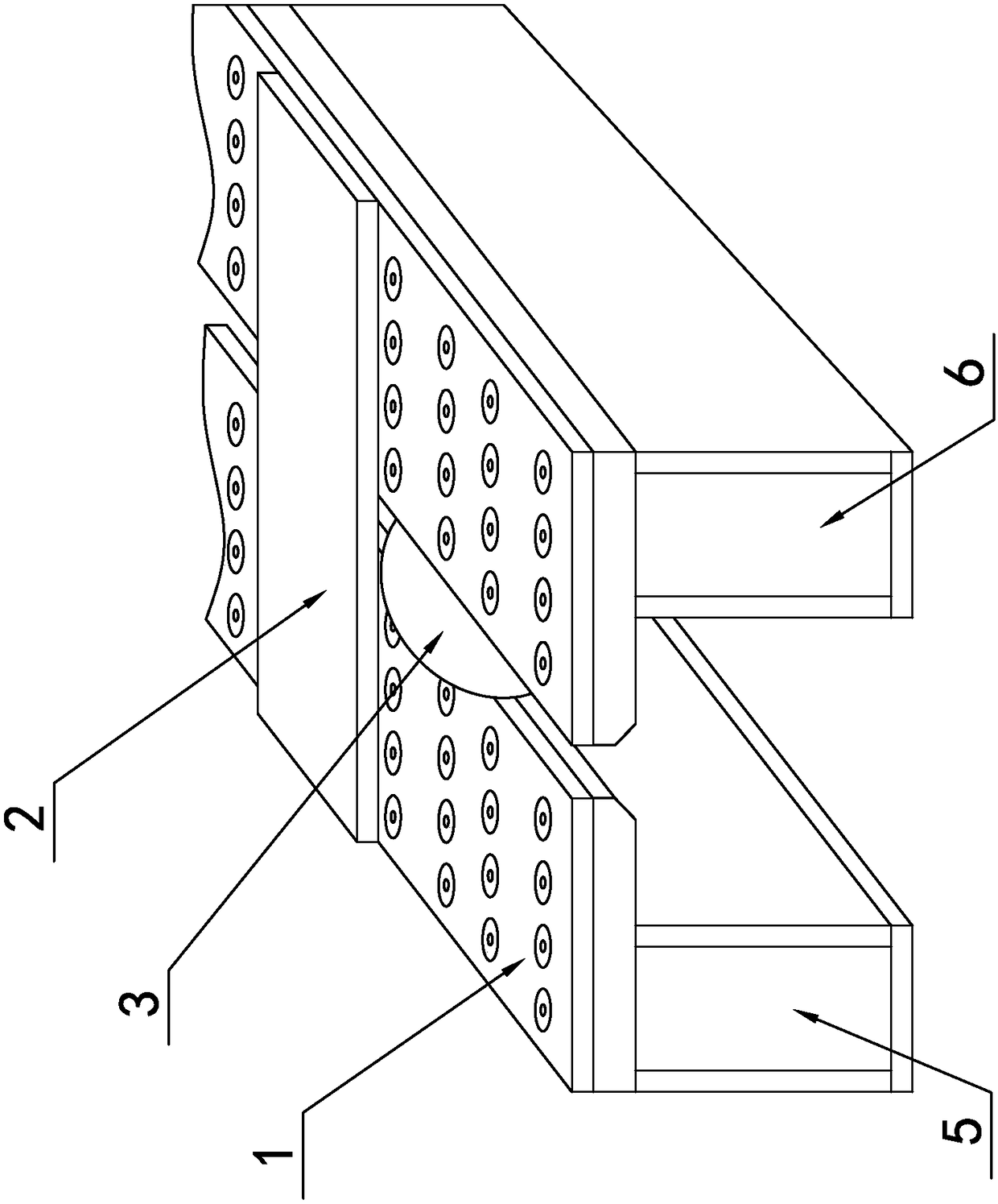
[0015] refer to figure 1 with figure 2 . The present invention is an air-floating workbench for a panel saw, which includes a base, a saw blade 3 installed on the base, and an air pump for generating compressed air. The upper surface of the base is uniformly provided with several air spray units 1, and each air spray unit 1 includes air holes 11 on the upper surface of the base, and the lower side of each air hole 11 is provided with a panel air groove 8, and the other side of the panel air groove 8 is connected with an air pump outlet 7. At this time, each air injection unit 1 can realize the air injection effect.
[0016] Each jet unit 1 also includes a spring 13 positioned in the air hole 11, a pneumatic floating ball arranged on the upper end of the spring 13 and a cover plate pressing the pneumatic floating ball 12, the cover plate is fixed on the orifice of the air hole 11, and the cover plate is provided with a diameter smaller than The round hole of the pneumatic f...
PUM
 Abstract
Description
Claims
Application Information