
Patsnap Eureka
For R&D, Patsnap Eureka makes reading and utilizing patents & technical documents easy.
Patsnap Eureka AIR
Designed for self-driven R&D workflows. Generate viable solutions, solve complex R&D challenges, empower your innovation with AI.

Patsnap Eureka Materials
Designed for material experts only. Revolutionize your material R&D, from search, analyze, to developing new materials.

TechResearch
Generate reliable direction feasibility study reports for your R&D in just a few steps.

TechSeek
Discover and master advanced knowledge NOW. Basics, ideas, possibilities, all at once.

TechMind
As an expert in R&D Theories, TechMind can generates customized viable solutions instantly.

TechRisk
Analyze your overall solution with one click, know your potential R&D risks in advance.

TechMonitor
Get weekly tech updates, stay abreast of the latest tech innovations and key insights.
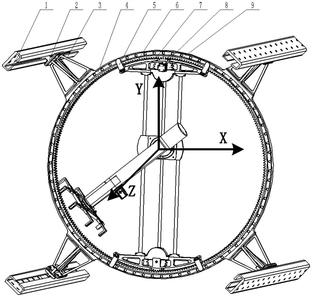
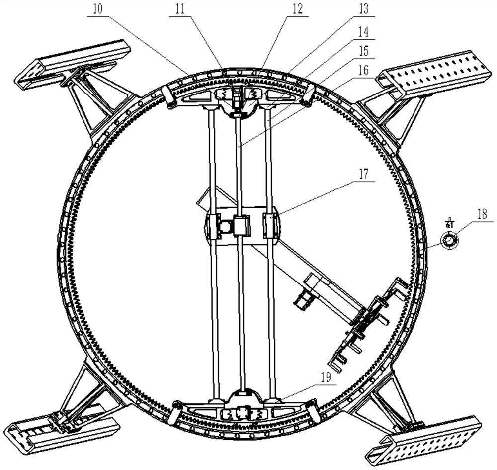
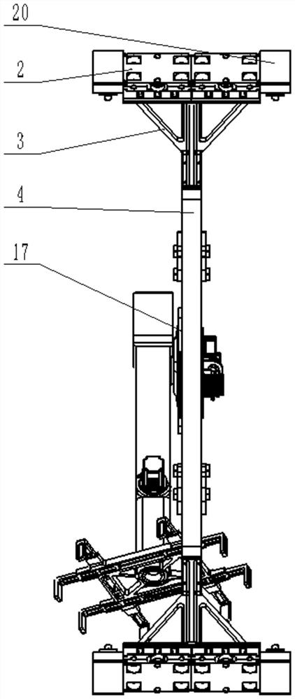
Six-degree-of-freedom annular tooling and delivery device for the space cabin
A carrier device and degree of freedom technology, applied in the direction of manufacturing tools, program-controlled manipulators, manipulators, etc., can solve the problems of inability to adjust the attitude of parts, small operating space, and large structural space, so as to improve the load capacity of equipment and reduce the overall Good size and force effect
- Summary
- Abstract
- Description
- Claims
- Application Information
AI Technical Summary
Problems solved by technology
Method used
Image

Examples
Embodiment Construction
[0025] exist figure 1 , figure 2 and image 3 In the schematic diagram of the six-degree-of-freedom annular tooling and carrying equipment shown, the annular outer bracket 4 and the inner gear ring 6 are fixed through an interference connection, and are fixed in the circumferential direction by a pin shaft 18. The inner bracket 7 of the inner bracket is provided with two pairs of cages 5 which are rotatably connected to the two ends of the inner bracket. The inner bracket is connected with the inner and outer rails on the outer bracket through the rotating rollers set in the cage, so that the inner bracket can be driven by the gear pair. Rotate around the outer bracket; Figure 5 and Figure 6As shown, the middle of the mobile platform 26 is provided with a screw nut support 33, and the two sides of the mobile platform are respectively provided with a self-lubricating bearing support 31, and the self-lubricating bearing 35 is axially fixed on the self-lubricating bearing t...
PUM
 Abstract
Description
Claims
Application Information
 - R&D Engineer
- R&D Manager
- IP Professional
- Industry Leading Data Capabilities
- Powerful AI technology
- Patent DNA Extraction
Browse by: Latest US Patents, China's latest patents, Technical Efficacy Thesaurus, Application Domain, Technology Topic, Popular Technical Reports.
© 2024 PatSnap. All rights reserved.Legal|Privacy policy|Modern Slavery Act Transparency Statement|Sitemap|About US| Contact US: help@patsnap.com