Dust removal fan linkage control system and reforming method of dust removal system

A technology of linkage control system and dust removal fan, which is applied in the direction of pump control, dust removal, machine/engine, etc., can solve the problems of wasting energy and production costs

Inactive Publication Date: 2018-08-07
上海联达节能科技股份有限公司
View PDF6 Cites 2 Cited by
  • Summary
  • Abstract
  • Description
  • Claims
  • Application Information

AI Technical Summary

Problems solved by technology

[0004] In order to solve the problems of energy waste and high production cost in the existing dust removal system, the present invention proposes a dust removal fan linkage control system, which includes an energy-saving regulator, a speed regulating device, an electric valve actuator, a wind pressure variable Conveyor and dust removal equipment operation status signal collector;

Method used


Image

  • Dust removal fan linkage control system and reforming method of dust removal system

Examples


Embodiment 1

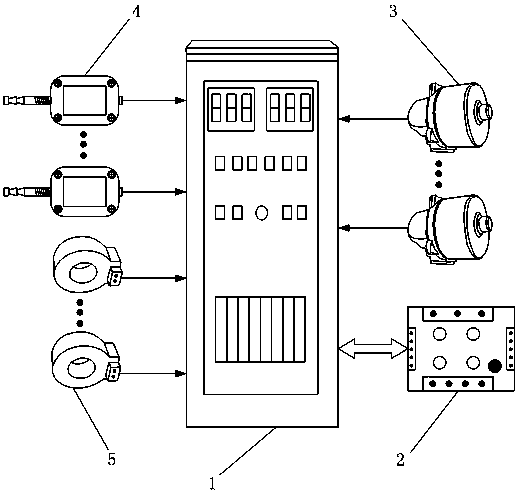
[0038] There are 3 screening production lines installed in parallel in the sintering plant. When only one of the screening production lines is turned on and the remaining two screening production lines are not working as backup, the non-working status collected by the dust removal equipment operation status signal collector 5 The operation status signal of the dust removal equipment on the two screening production lines is 0, and the operation status signal of the dust removal equipment on the working one screening production line is 1. The energy-saving controller 1 calculates the wind pressure range Q required for dust collection in the dust collection main pipeline of the dust removal system according to the dust removal equipment operation state signal collected by the dust removal equipment operation state signal collector 5, and compares the dust removal system with the non-working two The pipeline valve corresponding to the dust removal equipment on the screening product...

Embodiment 2

[0040]There are 3 screening production lines in parallel in the sintering plant. When the 3 screening production lines are all turned on, the dust removal equipment operation status signal collector 5 collects the operation status signals of the dust removal equipment on the 3 screening production lines. . The energy-saving controller 1 calculates the wind pressure range Q required for dust collection in the dust collection main pipeline of the dust removal system according to the dust removal equipment operation status signal collected by the dust removal equipment operation status signal collector 5, and connects the dust removal system with the three screening production lines The pipeline valves corresponding to the dust removal equipment on the system are all opened, so as to realize the automatic control of the pipeline valves corresponding to the dust collection point, and avoid the error and lag of manual adjustment. In addition, after the pipeline valves corresponding...


PUM


Abstract

The invention relates to the field of dust removal control, in particular to a dust removal fan linkage control system and a reforming method of a dust removal system, aiming to solve problems of waste of energy and high production cost in use of conventional dust removal systems. The dust removal fan linkage control system comprises a wind pressure transmitter, a dust removal equipment running state signal collector, a speed regulator, an electric valve actuator and an energy-saving regulator. The wind pressure transmitter acquires real wind pressure value P of the inside of a dust-collectingmain pipeline in real time and transmits the value to the energy-saving regulator; the dust removal equipment running state signal collector collects running state signals of the dust removal equipment and send them to the energy-saving regulator; the speed regulator is connected with the energy-saving regulator and the dust removal fan to regulate revolution speed of the dust removal fan; the electric valve actuator is connected with the energy-saving regulator and a pipeline valve to control on and off of the pipeline valve; the energy-saving regulator regulates revolution speed of the dustremoval fan and controls on and off of the pipeline valve through the electric valve actuator to keep the real wind pressure value P within a wind pressure range Q as needed for dust collection. Thedust removal fan linkage control system can save energy with production cost reduced.

Description

technical field [0001] The invention relates to the field of dust removal control, in particular to a dust removal fan linkage control system and a method for transforming the dust removal system. Background technique [0002] At present, in some production processes, dust pollution is relatively serious. Taking the sintering plant as an example, the sintered cake unloaded from the sintering machine is crushed into pieces with a particle size of less than 150mm by a single roller, and then sent to the ring cooler. After being cooled by the ring cooler, it is transported to the The finished product screening room carries out granulation, and is divided into large finished products with a particle size greater than 20mm, bottom material with a particle size of 12-20mm, small finished products with a size of 5-12mm, and returned ore materials with a particle size of less than 5mm; the specific screening process adopts three screening processes, that is, Each sintering machine ...

Claims


Application Information

Patent Timeline
Patent Type & Authority Applications(China)
IPC IPC(8): F04D27/00B08B15/04
CPCF04D27/00B08B15/04F04D27/001F04D27/004
Inventor 丁炳刚皮建国林振楠王宗旭安广宁
Owner 上海联达节能科技股份有限公司
Why Eureka
Try Eureka